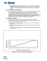
10-10
Page 51
2008-10-01
6. BLOWER PACKS (BOBP, RMBP)
WARNING
STEAM DISTRIBUTOR ON THE BUILT-ON AND REMOTE BLOWER
PACKS HAVE A HOT SURFACE THAT COULD RESULT IN BURNS IF
TOUCHED. NORTEC RECOMMENDS MOUNTING AT LEAST 8 FEET
ABOVE THE FLOOR.
A.
BLOWER PACKS
(1) Optional blower packs are used to distribute steam to localized areas such as computer
rooms or in areas that do not have a built-in air distribution system.
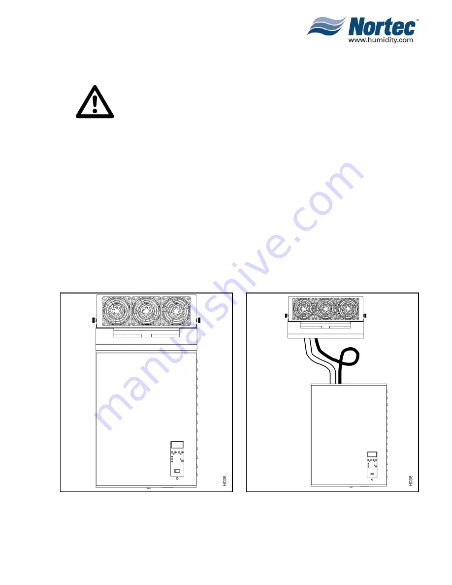
(2) Blower packs are available integrally mounted on humidifier BOBP, (See Figure 27.) or
detached and field-piped and wired to humidifier RMBP. (See Figure 28.)
(3) Blower packs consist of a matching powder coated steel cabinet containing: three axial
blowers with finger guards powered by 120 VAC or line voltage humidifiers, with built-in
multi-tap transformer (when necessary), fuse, high temperature plastic distributor with
stainless steel lid, horizontal and vertical adjustment knobs for directional control, built-
in thermostat to activate blowers, speed control rocker switch and safety loop relay.
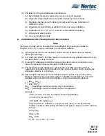
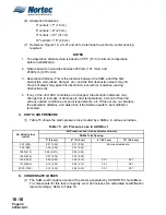
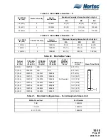
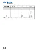
(4) Refer to Table 22 for ceiling and frontal clearances required for blower packs.
Dimensions apply to both built-on and remote-mounted versions of blower packs.
(5) Mount remote blower pack(s) using factory supplied wall mounting bracket with
clearances as recommended in Table 22.
Figure 28. NH Series Remote Mounted
Blower Pack
Figure 27. NH Series Humidifier With
Built-On Blower Pack
Summary of Contents for NHPC
Page 1: ...2538144 B NH Series NHTC NHPC ELECTRODE STEAM HUMIDIFIER Engineering Manual TM ...
Page 9: ...10 00 Page 1 2008 10 01 10 00 INTRODUCTION ...
Page 10: ...10 00 Page 2 2008 10 01 Figure 1 NHTC ...
Page 13: ...10 00 Page 5 2008 10 01 Figure 2 Optimum Boiling Time Figure 3 Conductivity ...
Page 18: ...10 00 Page 10 2008 10 01 Figure 6 Typical NHRS Installation Sheet 1 of 2 ...
Page 19: ...10 00 Page 11 2008 10 01 Figure 7 Typical NHRS Installation Sheet 2 of 2 ...
Page 20: ...10 10 Page 12 2008 10 01 10 10 HUMIDITY STEAM ABSORPTION AND DISTRIBUTION ...
Page 35: ...10 10 Page 27 2008 10 01 Figure 2 Psychrometric Chart ...
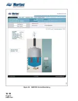
Page 64: ...10 10 Page 56 2008 10 01 Figure 30 NORTEC OnLine Monitoring ...
Page 71: ...10 20 Page 63 2008 10 01 10 20 SPECIFICATIONS ...
Page 81: ...10 30 Page 73 2008 10 01 10 30 SUBMITTALS ...
Page 86: ...10 30 Page 78 2008 10 01 Figure 2 Primary Line Voltage Wiring to Unit ...
Page 87: ...10 30 Page 79 2008 10 01 Figure 3 Physical Data NHTC NHPC 005 030 ...
Page 88: ...10 30 Page 80 2008 10 01 Figure 4 Physical Data NHTC NHPC 050 100 ...
Page 89: ...10 30 Page 81 2008 10 01 Figure 5 Physical Data NHTC NHPC 150 200 ...
Page 96: ...10 30 Page 88 2008 10 01 Figure 12 In Duct AHU Installation With Mounting Frame Installation ...
Page 98: ...10 30 Page 90 2008 10 01 Figure 13 In Duct AHU Installation With Mounting Frame Installation ...
Page 100: ...10 30 Page 92 2008 10 01 Figure 16 Atmospheric SAM e Adapter Dimensions ...
Page 101: ...10 30 Page 93 2008 10 01 Figure 17 Atmospheric Steam Header and Adapter Configuration ...
Page 102: ...10 30 Page 94 2008 10 01 Figure 18 Physical Data for Remote Mounted Blower Pack ...
Page 103: ...10 30 Page 95 2008 10 01 Figure 19 Physical Data Units with Optional Built On Blower Packs ...
Page 104: ...10 30 Page 96 2008 10 01 Figure 20 Physical Data Units with Optional Built On Blower Packs ...


