10-10
Page 54
2008-10-01
(d) Modulating Demand Signal Supplied by Others – A signal that is a linear demand
signal that rises on need for humidity can be used in conjunction with NORTEC
humidifiers. See features section for a list of which models can accept which
signal)
D.
OUTDOOR TEMPERATURE SETBACK
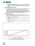
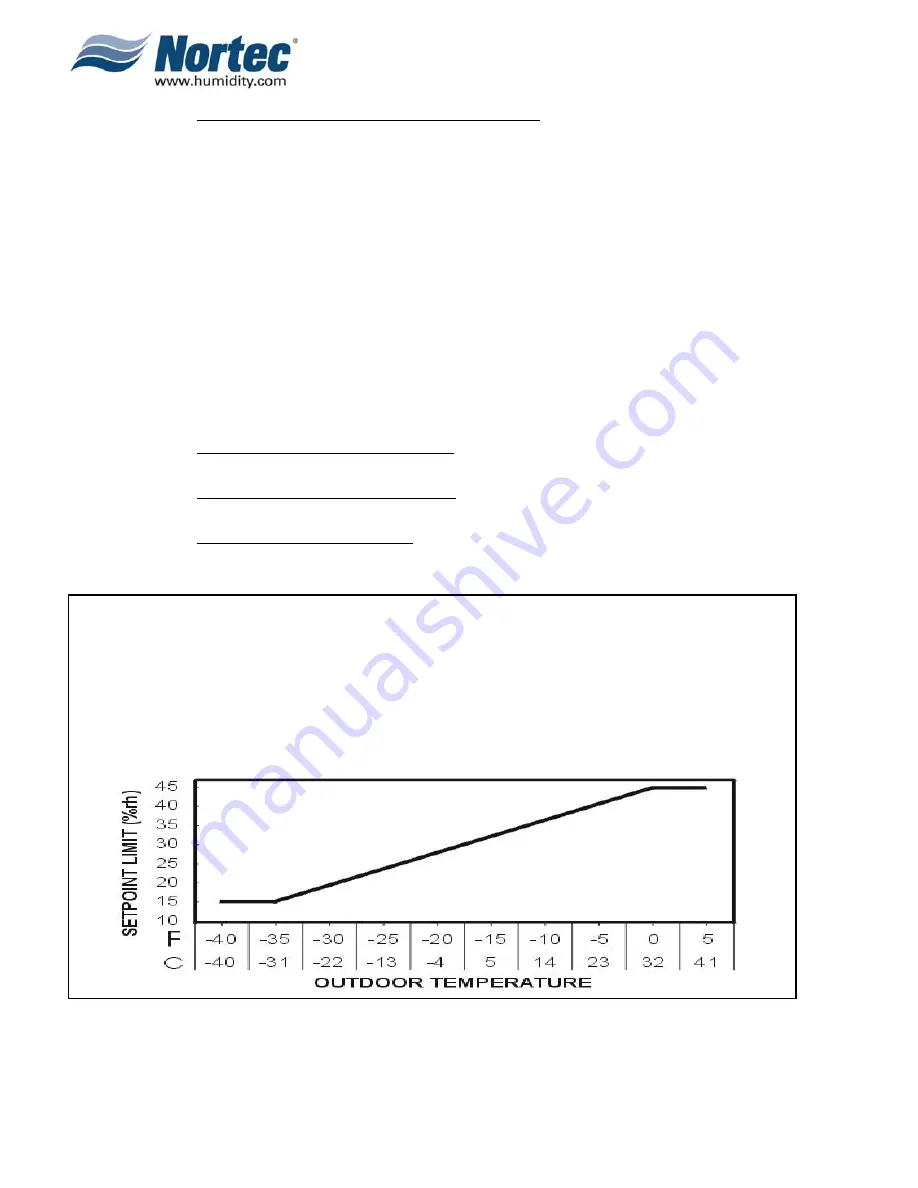
(1) The outdoor temperature setback sensor is used to prevent condensation on windows
or other surfaces that are adjacent to outdoor air. This sensor can be used in
conjunction with the NORTEC controls mentioned above (both the on/off and
modulating demand signal controllers) The sensor allows the controller to override the
set point to prevent the humidifier from humidifying when condensation could be
possible. (See Figure 29.) Locate the temperature sensor near the fresh air intake. This
will ensure accurate representation of the outdoor air temperature.
E.
TRANSDUCER SENSORS
(1) Transducer Sensors are signals sent back to either a controller or back to the
humidifier. Limited models can accept a direct transducer signal. (See features section
for each specific model) The sensors include:
(a) Wall Mounted Humidity Transducer – Sensor, output of 2-10 VDC, range of 0 to
95% rh.
(b) Duct Mounted Humidity Transducer – Sensor, output of 2-10 VDC, range of 0 to
95% rh.
(c) Transducer Sensor By Others – Humidity sensors that rise linearly with the sensed
rh in the room.
Figure 29. Set Point Versus Outdoor Temperature
Summary of Contents for NHPC
Page 1: ...2538144 B NH Series NHTC NHPC ELECTRODE STEAM HUMIDIFIER Engineering Manual TM ...
Page 9: ...10 00 Page 1 2008 10 01 10 00 INTRODUCTION ...
Page 10: ...10 00 Page 2 2008 10 01 Figure 1 NHTC ...
Page 13: ...10 00 Page 5 2008 10 01 Figure 2 Optimum Boiling Time Figure 3 Conductivity ...
Page 18: ...10 00 Page 10 2008 10 01 Figure 6 Typical NHRS Installation Sheet 1 of 2 ...
Page 19: ...10 00 Page 11 2008 10 01 Figure 7 Typical NHRS Installation Sheet 2 of 2 ...
Page 20: ...10 10 Page 12 2008 10 01 10 10 HUMIDITY STEAM ABSORPTION AND DISTRIBUTION ...
Page 35: ...10 10 Page 27 2008 10 01 Figure 2 Psychrometric Chart ...
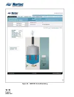
Page 64: ...10 10 Page 56 2008 10 01 Figure 30 NORTEC OnLine Monitoring ...
Page 71: ...10 20 Page 63 2008 10 01 10 20 SPECIFICATIONS ...
Page 81: ...10 30 Page 73 2008 10 01 10 30 SUBMITTALS ...
Page 86: ...10 30 Page 78 2008 10 01 Figure 2 Primary Line Voltage Wiring to Unit ...
Page 87: ...10 30 Page 79 2008 10 01 Figure 3 Physical Data NHTC NHPC 005 030 ...
Page 88: ...10 30 Page 80 2008 10 01 Figure 4 Physical Data NHTC NHPC 050 100 ...
Page 89: ...10 30 Page 81 2008 10 01 Figure 5 Physical Data NHTC NHPC 150 200 ...
Page 96: ...10 30 Page 88 2008 10 01 Figure 12 In Duct AHU Installation With Mounting Frame Installation ...
Page 98: ...10 30 Page 90 2008 10 01 Figure 13 In Duct AHU Installation With Mounting Frame Installation ...
Page 100: ...10 30 Page 92 2008 10 01 Figure 16 Atmospheric SAM e Adapter Dimensions ...
Page 101: ...10 30 Page 93 2008 10 01 Figure 17 Atmospheric Steam Header and Adapter Configuration ...
Page 102: ...10 30 Page 94 2008 10 01 Figure 18 Physical Data for Remote Mounted Blower Pack ...
Page 103: ...10 30 Page 95 2008 10 01 Figure 19 Physical Data Units with Optional Built On Blower Packs ...
Page 104: ...10 30 Page 96 2008 10 01 Figure 20 Physical Data Units with Optional Built On Blower Packs ...


