10-10
Page 59
2008-10-01
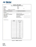
NORTEC ONLINE CONFIGURATION FORM
Please complete the information below.
Attention:
Date:
Company:
Fax #:
From:
Page:
of
Subject:
NORTEC Online Information
G
FOR YOUR INFORMATION
G
RESPONSE REQUESTED
Agent P.O. Number: ____________________
Sales Order Number: ____________________
Desired NORTEC Online Connection Type:
Static IP connection
DHCP (dynamic IP)
GPRS connection
Dial-up modem connection
Settings for Static IP Connection:
Module IP Address:
____________________
Subnet Mask:
____________________
Default Gateway Address: ____________________
Primary DNS:
____________________
Secondary DNS:
____________________
Setting for GPRS Connection:
User Name:
____________________
Password/PIN Code: ____________________
APN String:
____________________
Connection String:
____________________
Settings for Dial-up Modem Connection:
User Name:
____________________
Password:
____________________
Phone Number to dial: ____________________
Be sure to include complete dial-up number string such as area code if
necessary.
Humidifier Ordering
Email Addresses for Event Notification:
Email Contact 1: ____________________
Email Contact 2: ____________________
Email Contact 3: ____________________
End User Information
Time Zone:
____________________
Company Name:
____________________
Address:
____________________
____________________
____________________
Phone Number:
____________________
Main Contact Person: ____________________
Humidifier
Model/Size
Unit
Designation
Desired Unit
Order
Lead Humidifier
Unit 1
Unit 2
Unit 3
Unit 4
Unit 5
Unit 6
Unit 7
Unit 8
Figure 31. NORTEC Online Configuration Form
Summary of Contents for NHPC
Page 1: ...2538144 B NH Series NHTC NHPC ELECTRODE STEAM HUMIDIFIER Engineering Manual TM ...
Page 9: ...10 00 Page 1 2008 10 01 10 00 INTRODUCTION ...
Page 10: ...10 00 Page 2 2008 10 01 Figure 1 NHTC ...
Page 13: ...10 00 Page 5 2008 10 01 Figure 2 Optimum Boiling Time Figure 3 Conductivity ...
Page 18: ...10 00 Page 10 2008 10 01 Figure 6 Typical NHRS Installation Sheet 1 of 2 ...
Page 19: ...10 00 Page 11 2008 10 01 Figure 7 Typical NHRS Installation Sheet 2 of 2 ...
Page 20: ...10 10 Page 12 2008 10 01 10 10 HUMIDITY STEAM ABSORPTION AND DISTRIBUTION ...
Page 35: ...10 10 Page 27 2008 10 01 Figure 2 Psychrometric Chart ...
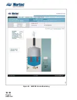
Page 64: ...10 10 Page 56 2008 10 01 Figure 30 NORTEC OnLine Monitoring ...
Page 71: ...10 20 Page 63 2008 10 01 10 20 SPECIFICATIONS ...
Page 81: ...10 30 Page 73 2008 10 01 10 30 SUBMITTALS ...
Page 86: ...10 30 Page 78 2008 10 01 Figure 2 Primary Line Voltage Wiring to Unit ...
Page 87: ...10 30 Page 79 2008 10 01 Figure 3 Physical Data NHTC NHPC 005 030 ...
Page 88: ...10 30 Page 80 2008 10 01 Figure 4 Physical Data NHTC NHPC 050 100 ...
Page 89: ...10 30 Page 81 2008 10 01 Figure 5 Physical Data NHTC NHPC 150 200 ...
Page 96: ...10 30 Page 88 2008 10 01 Figure 12 In Duct AHU Installation With Mounting Frame Installation ...
Page 98: ...10 30 Page 90 2008 10 01 Figure 13 In Duct AHU Installation With Mounting Frame Installation ...
Page 100: ...10 30 Page 92 2008 10 01 Figure 16 Atmospheric SAM e Adapter Dimensions ...
Page 101: ...10 30 Page 93 2008 10 01 Figure 17 Atmospheric Steam Header and Adapter Configuration ...
Page 102: ...10 30 Page 94 2008 10 01 Figure 18 Physical Data for Remote Mounted Blower Pack ...
Page 103: ...10 30 Page 95 2008 10 01 Figure 19 Physical Data Units with Optional Built On Blower Packs ...
Page 104: ...10 30 Page 96 2008 10 01 Figure 20 Physical Data Units with Optional Built On Blower Packs ...


