10-20
Page 67
2008-10-01
m
Manual capacity output adjustment range of 20-100%.
n
Humidifier model, capacity, software version.
o
Cylinder model # and capacity rating.
p
Humidifier run time weighted hours.
q
Date and time (year, month, day, hour and minute).
r
Stand by heating to increase steam production response time.
s
Rapid modulation capability reduces response time upon start-up.
t
Short cycling detection and correction diagnostics.
u
Foam detection and correction capability.
v
Scroll through start-up and troubleshooting checklist on graphical display.
w
Self-diagnostics during start-up to system test to prevent unsafe operation
of the unit(s).
x
User adjustable drain/flush frequency.
HUMIDIFIER CONTROLS NHPC
(b) Proportional Controller microprocessor with following features or functions:
1
Graphic function display with user interface with touch type key pad.
2
Acceptance of industry standard [analogue continuous control demand signal
[0-1Vdc] [1-5Vdc] [0-10 Vdc] [2-10 Vdc] [0-16 Vdc] [0-20 mA]
3
Keypad/Display to monitor and control humidifier parameters.
a
System demand in lbs/hr (kg/hr).
b
Security loop status open/close.
c
Control Channel 1 demand %.
d
Manual capacity output adjustment range of 20-100%.
e
Self-diagnostics during start-up to system test to prevent undase
operation of the Unit[s].
f
Control signal type.
g
Software version.
(c)
1
Internal communications via Modbus RTU protocol provides monitoring and
control allowing humidifier(s) to communicate to Building Management
System (BMS). Supporting a RS485 port with a configuration of 9600bps,
8-bits, no parity, one stop bit shall support the following variables:
a
Change Cylinder – Indicates cylinder needs to be replaced (read).
b
Channel 1 Input – Humidifier input value being supplied to channel 0-
100% (read/write).
c
Channel 1 Set point – Control channel 1 setpoint for relative humidity in
space 0-100% (read/write).
d
Channel 2 Input – Humidifier input value being supplied to channel 0-
100% (read/write).
Summary of Contents for NHPC
Page 1: ...2538144 B NH Series NHTC NHPC ELECTRODE STEAM HUMIDIFIER Engineering Manual TM ...
Page 9: ...10 00 Page 1 2008 10 01 10 00 INTRODUCTION ...
Page 10: ...10 00 Page 2 2008 10 01 Figure 1 NHTC ...
Page 13: ...10 00 Page 5 2008 10 01 Figure 2 Optimum Boiling Time Figure 3 Conductivity ...
Page 18: ...10 00 Page 10 2008 10 01 Figure 6 Typical NHRS Installation Sheet 1 of 2 ...
Page 19: ...10 00 Page 11 2008 10 01 Figure 7 Typical NHRS Installation Sheet 2 of 2 ...
Page 20: ...10 10 Page 12 2008 10 01 10 10 HUMIDITY STEAM ABSORPTION AND DISTRIBUTION ...
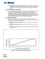
Page 35: ...10 10 Page 27 2008 10 01 Figure 2 Psychrometric Chart ...
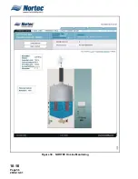
Page 64: ...10 10 Page 56 2008 10 01 Figure 30 NORTEC OnLine Monitoring ...
Page 71: ...10 20 Page 63 2008 10 01 10 20 SPECIFICATIONS ...
Page 81: ...10 30 Page 73 2008 10 01 10 30 SUBMITTALS ...
Page 86: ...10 30 Page 78 2008 10 01 Figure 2 Primary Line Voltage Wiring to Unit ...
Page 87: ...10 30 Page 79 2008 10 01 Figure 3 Physical Data NHTC NHPC 005 030 ...
Page 88: ...10 30 Page 80 2008 10 01 Figure 4 Physical Data NHTC NHPC 050 100 ...
Page 89: ...10 30 Page 81 2008 10 01 Figure 5 Physical Data NHTC NHPC 150 200 ...
Page 96: ...10 30 Page 88 2008 10 01 Figure 12 In Duct AHU Installation With Mounting Frame Installation ...
Page 98: ...10 30 Page 90 2008 10 01 Figure 13 In Duct AHU Installation With Mounting Frame Installation ...
Page 100: ...10 30 Page 92 2008 10 01 Figure 16 Atmospheric SAM e Adapter Dimensions ...
Page 101: ...10 30 Page 93 2008 10 01 Figure 17 Atmospheric Steam Header and Adapter Configuration ...
Page 102: ...10 30 Page 94 2008 10 01 Figure 18 Physical Data for Remote Mounted Blower Pack ...
Page 103: ...10 30 Page 95 2008 10 01 Figure 19 Physical Data Units with Optional Built On Blower Packs ...
Page 104: ...10 30 Page 96 2008 10 01 Figure 20 Physical Data Units with Optional Built On Blower Packs ...


