background image


10-30 

Page 82 

2008-10-01


Unit Model 

NH 005-020 

NH 030 

NH 045-100 

NH 135-200 

Distributor Model 

ASD BSD 

CSD 

CSD 

No. of Cylinders 

1 1 

No. of Outlets/Cylinder 

1 1 

OD of Cylinder Outlet (NHTC,P,B) 

f" f" 

f" 

1¾" 

OD of Cylinder Outlet (NHSC/DI) 

1¾" 1¾" 

1¾" 

1¾" 


Distributor 
Model 

Dimensions – in.(mm) 

Minimum Duct 


Length –         

in. (mm) 

ASD 12 

2 (51) 

1.75 (44) 

10 (254) 

12 (305) 

ASD18 

2 (51) 

1.75 (44) 

16 (406) 

18 (457) 

ASD 24 

2.25 (57) 

1.75 (44) 

20 (508) 

24 (609) 

ASD 30 

2.25 (57) 

1.75 (44) 

26 (660) 

30 (762) 

ASD 36 

2.25 (57) 

1.75 (44) 

32 (813) 

36 (914) 

ASD 42 

2.5 (64) 

2 (51) 

38 (965) 

42 (1066) 

ASD 48 

2.5 (64) 

2 (51) 

44 (1118) 

48 (1219) 

ASD 54 

2.5 (64) 

2 (51) 

50 (1270) 

54 (1371) 

ASD 60 

3 (76) 

2.5 (64) 

56 (1422) 

60 (1524) 

ASD 66 

3 (76) 

2.5 (64) 

62 (1575) 

66 (1676) 


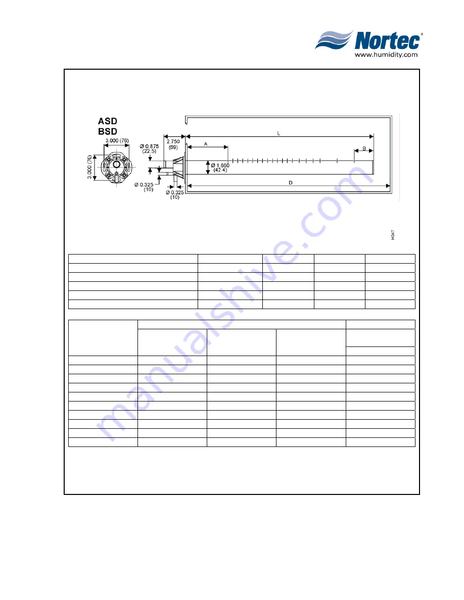
Figure 6.  Distributor Dimensions (Sheet 1 of 3) 


Summary of Contents for NHPC

Page 1: ...2538144 B NH Series NHTC NHPC ELECTRODE STEAM HUMIDIFIER Engineering Manual TM ...

Page 2: ...ersonnel or the use of parts components equipment that are not authorized or approved by NORTEC COPYRIGHT NOTICE Copyright 2008 WALTER MEIER LTD All rights reserved SPECIFICATION LABEL LOCATION The Specification Label for your NH Series humidifier is located on the bottom of the unit You will find it attached to the skirt that separates the electrical and plumbing compartments on the electrical co...

Page 3: ...EAM HUMIDITY LEVEL 30 C CONTROL OF DUCT OR PLENUM SATURATION 31 3 STEAM RUNS AND CONDESNATE RETURNS 32 A STEAM RUNS 32 B CONDENSATE RETURN 34 4 STEAM DISTRIBUTORS ASD BSD CSD 37 A STEAM DISTRIBUTORS 37 B DISTRIBUTOR CHARACTERISTICS 37 C DISTRIBUTOR LOCATIONS AND MOUNTING 38 D MULTIPLE DISTRIBUTOR APPLICATIONS 38 E LOCATION OF STEAM DISTRIBUTORS WITHIN AN AIR HANDLER 40 F DISTRIBUTOR ABSORPTION DIS...

Page 4: ...G CONTROLS AND SENSORS 55 G NORTEC ONLINE 55 H NORTEC LINKS 57 I TYPICAL INSTALLATION LAYOUT FOR NHTC NHPC 58 J NORTEC CONTROLLER DIMENSIONS 58 10 20 SPECIFICATIONS 1 HUMIDIFIERS 64 A GENERAL 64 B PRODUCTS 64 C EXECUTION 70 10 30 SUBMITTALS 1 SUBMITTAL DESCRIPTIONS 74 A INTRODUCTION 74 B NH UNIT 74 C DISTRIBUTORS 74 D SAM e 74 E BLOWER PACK 74 F CONTROLS 75 WARRANTY ...

Page 5: ...m Distributor Installation Minimum Clearance 38 Figure 12 Cutting Duct For Mounting 39 Figure 13 Humidification Distance Nomogram 39 Figure 14 Best Location for Multiple Steam Distributors 40 Figure 15 Roof Top Units 2 20 Tons Typical Location 41 Figure 16 Small Units On Residential Furnaces 41 Figure 17 SAM e Tubes 42 Figure 18 Cross Section of Distributor Pipe 42 Figure 19 Absorption Distance 3 ...

Page 6: ... Data NHTC NHPC 005 030 79 Figure 4 Physical Data NHTC NHPC 050 100 80 Figure 5 Physical Data NHTC NHPC 150 200 81 Figure 6 Distributor Dimensions 3 Sheets 82 Figure 7 SAM e General Dimensions 85 Figure 8 General Mini SAM e Dimensions 86 Figure 9 In Duct AHU Installation Without Mounting Frame Installation 87 Figure 10 In Duct AHU Installation With Mounting Frame Installation 88 Figure 11 Outside ...

Page 7: ...r 30 Table 11 Steam Line Material 33 Table 12 Recommended Material and Size for Steam Run 33 Table 13 Recommended Condensate Line at Distributor s 33 Table 14 Maximum Recommended Length of Steam Runs 34 Table 15 Air Pressure Loss in AHU Duct 44 Table 16 Condensate Loss 46 Table 17 SAM e Tube Matrix 48 Table 18 Mini SAM e Headers 3 49 Table 19 Mini SAM e Headers 6 49 Table 20 Mini SAM e Tubes 49 Ta...

Page 8: ...gnal By Others Single Channel 113 Table 14 Modulating Demand Signal By Others Dual Channel 113 Table 15 Modulating By Other Transducer Signal 113 Table 16 NORTEC OnLine Options 114 Table 17 NORTEC Links Options 114 Table 18 NH Series Fusing Options 114 ...

Page 9: ...10 00 Page 1 2008 10 01 10 00 INTRODUCTION ...

Page 10: ...10 00 Page 2 2008 10 01 Figure 1 NHTC ...

Page 11: ...d A PROPORTIONAL INTEGRAL AUTO ADAPTIVE CONTROL SYSTEM FOR THE NHTC NHPC 1 NORTEC s patented P I Auto Adaptive control system allows the unit to operate at an optimal low water level using the same fixed electrode spacing regardless of the incoming water conditions Boiling of the water allows the minerals in the water to remain behind in the cylinder This raises the contained water conductivity to...

Page 12: ...des this added feedback 10 The proportional P and integral I factors have been weighted as to the relative influence each will have when the NHTC NHPC calculates a drain The preprogrammed weighing was derived through extensive field and laboratory tests When supply water conductivity is extremely high requiring substantially more drains the NHTC NHPC will see the pattern developing in cycles store...

Page 13: ...10 00 Page 5 2008 10 01 Figure 2 Optimum Boiling Time Figure 3 Conductivity ...

Page 14: ...e minerals will be removed during short flush cycles within the cylinder Therefore the water chemistry the unit running time and output capacity setting ultimately determines the cylinder life See Figure 3 Output vs Cylinder Life a As minerals build up on the electrodes in the cylinder of the NORTEC NH Series humidifier the patented P I Auto Adaptive control system automatically raises the water l...

Page 15: ...thoroughly during boiling 3 Boil from C to D while monitoring time T actual 4 Decide how long how much to drain then fill to B 5 Drain according to the P I calculated drain time fill on to control outlet temperature 6 At D stop draining and postpone remaining drain fill to B 7 Continue remaining drain 8 With drain finished fill to A 9 Boil to D timing from C to D 10 Decide how long to drain in thi...

Page 16: ...s the drain water to 140 F 60 C or less NOTE The electrode steam process provides optimum efficiency because all resistance to current passage is converted to usable energy Unlike cal rod or infrared humidifiers which convert some of their capacities into unusable heat Figure 5 Capacity Setting Cylinder Life Figure 6 Output vs Service Life ...

Page 17: ...ted on the humidifier s specification label 2 Ensure that the external fuse disconnect is sufficient size to handle the rated amperage as indicated on the humidifier s specifications label Refer to local building codes 3 Report any discrepancy immediately to the site engineer 4 Location and mounting is described in Chapter 10 10 5 For typical installation see Figures 6 7 ...

Page 18: ...10 00 Page 10 2008 10 01 Figure 6 Typical NHRS Installation Sheet 1 of 2 ...

Page 19: ...10 00 Page 11 2008 10 01 Figure 7 Typical NHRS Installation Sheet 2 of 2 ...

Page 20: ...10 10 Page 12 2008 10 01 10 10 HUMIDITY STEAM ABSORPTION AND DISTRIBUTION ...

Page 21: ...ine the humidification load three basic values need to be known a The design conditions of the humidified space i e the temperature and humidity required b The conditions of the incoming air i e the temperature and humidity available c Incoming air volume and secondary conditions that can affect the humidification load 2 Data and calculations required to estimate humidification load are described ...

Page 22: ... 0 0 0 0 0 0 0 0 20 10 5 0 5 10 15 20 25 30 35 40 45 50 Outdoor temperature Chart shows what the residual indoor RH would be at 70 F under varying outdoor conditions if a proper humidification system were not installed in the building Studies indicate that the recommended RH should be between 40 and 60 for optimum benefits to the occupants Determine the moisture required in the space Table 3 Grain...

Page 23: ...AC system if this feature is included in the system 2 For maximum accuracy all three should be estimated and the largest chosen C F Grains C F Grains C F Grains C F Grains C F Grains C F Grains 23 10 29 4 40 2 86 58 5 41 76 9 75 35 95 17 28 114 29 34 5 35 41 2 97 59 5 60 77 10 06 96 17 80 115 30 13 18 0 48 42 3 08 16 60 5 80 78 10 40 97 18 31 49 120 34 38 8 61 43 3 20 61 6 00 79 10 80 98 18 85 125...

Page 24: ...1 68 69 80 35 37 35 Idaho Boise Lewiston 23 20 10 5 82 79 75 73 74 71 95 95 54 64 34 37 23 25 35 35 Illinois Cairo Chicago Peoria 18 23 23 0 10 10 81 81 83 69 70 72 75 77 98 95 96 83 78 81 57 51 53 55 58 37 35 35 Indiana Fort Wayne Indianapolis Terre Haute 23 23 18 10 10 0 84 83 82 75 72 70 81 78 76 95 95 95 84 84 77 53 54 50 58 60 56 35 35 35 Iowa Davenport Sioux City 26 29 15 20 78 67 72 95 95 8...

Page 25: ...e 18 0 73 60 67 93 79 57 73 34 South Carolina Charleston Columbia 9 12 15 10 87 81 55 57 76 65 95 95 88 83 64 56 82 68 35 35 South Dakota Huron Rapid City 29 29 20 20 79 71 72 69 76 67 95 95 86 71 52 42 49 40 35 35 Tennessee Knoxville Memphis 18 18 0 0 83 82 65 67 69 73 95 95 83 85 55 55 66 59 35 35 Texas Amarillo Corpus Christi Dallas El Paso Houston San Antonio 23 7 12 12 7 7 10 20 10 10 20 20 7...

Page 26: ...8 17 15 0 1 5 83 84 83 83 84 76 50 56 70 28 29 24 Ontario Thunder Bay Hamilton Kaspuskasing Kingston Kitchener London North Bay Ottawa Peterborough Sioux Lookout Sudbury Timmins Toronto Windsor Sault St Marie 33 18 34 24 19 18 29 27 25 36 29 36 19 16 29 27 0 30 11 3 0 20 17 13 33 20 33 3 3 20 80 75 79 84 80 77 77 78 81 79 82 86 91 87 85 88 90 87 90 90 65 89 90 90 92 88 52 52 52 69 58 53 46 50 53 6...

Page 27: ...r print shop has a floor area of 100 x 100 with a 20 ceiling with a large amount of traffic This requires 100 x 100 x 20 x 2 400 000 ft3 hr Using our example the moisture required is 400 000 x 5 08 _______________ 290 lbs hr 7000 grains lb 4 Using make up air a Formula 4 Assume our print shop has a 15 000 CFM HVAC system and uses 10 make up air during winter The amount of outside make up air enter...

Page 28: ...the required supply air volume When the outdoor air temperature is higher than the supply air temperature required to maintain cooling but is lower than the return air temperature the make up air and exhaust air dampers are 100 open The recirculation air damper closes and the building refrigeration system provides the portion of cooling load that cannot be provided by outside air intake d From thi...

Page 29: ...f these materials that are constantly introduced to the area its affects must be considered c Table 7 identifies many recommended indoor conditions for various locations and processes these can be of use when deciding what conditions would be most beneficial in your application d In Figure 2 you will find the ASHRAE physchrometric chart describing the enthalpy of dry air and the effects to and fro...

Page 30: ...r Writing 3 Ash 3 2 2 1 2 4 3 0 4 2 3 2 3 7 4 2 5 0 4 0 4 7 5 2 5 6 4 7 5 5 6 2 6 2 6 1 6 5 7 2 6 9 7 2 7 5 8 3 8 1 8 7 8 8 9 9 10 3 10 6 10 8 11 9 13 9 13 2 14 2 Textile Cotton Absorbent Cotton American cloth Cotton Sea Isle roving Hemp Manila and Sisal Jute Average Grade Linen Dried Spun Yarn Rayon Celulose Acetate Fibre Rayon Cupramonium Average Skein Rayon Viscose Nitrocel Silk Raw Chevennes S...

Page 31: ...ssing Polishing Pan Supply Air Pan Rooms Nonpareil Pan Supply Air Hard Candy Cooling Tunnel Supply Air Hard Candy Packing Hand Candy Storage Caramel Rooms 55 62 80 85 40 45 62 40 45 65 75 80 75 78 110 125 150 100 50 65 85 105 70 80 75 80 100 120 60 70 70 75 50 70 70 80 13 17 27 29 4 7 17 4 7 18 24 27 24 26 43 52 66 38 10 18 29 41 21 27 24 27 38 49 16 21 21 24 10 21 21 27 45 55 25 30 70 85 45 70 85...

Page 32: ...rust Runner Hopping Processing Selenium and Copper Oxide Plates 72 68 70 76 72 76 73 75 68 76 70 74 22 20 21 24 22 24 23 24 20 24 21 23 15 40 50 55 50 55 40 45 60 63 50 65 70 20 40 30 60 30 50 30 40 Fruit Storage Apples Apricots Grapefruits California Grapefruits Florida Grapes Eastern Grapes Western Lemons Oranges California Oranges Florida Peaches and Nectarines Plums Specialty Citrus Fruit 30 4...

Page 33: ... Room Table Compressing and Coating Effervescent Tablets and Powders Hypodermic Tablets Colloids Cough Drops Glandular Products Ampoule Manufacturing Gelatin Capsules and Storage Microanalysis Biological Manufacturing and Liver Extracts Serums Animal Rooms 75 75 75 75 70 80 76 75 76 76 76 76 75 80 24 24 24 24 21 27 24 24 24 24 24 24 24 27 35 35 20 30 30 50 40 5 10 35 50 35 50 35 50 50 Plastics Man...

Page 34: ...80 70 75 75 80 70 75 75 80 75 80 70 75 75 80 70 75 75 80 70 75 75 80 75 80 70 75 75 80 75 80 70 75 75 80 70 75 75 80 75 80 70 75 76 76 75 80 75 80 70 75 24 27 21 24 24 27 24 27 21 24 24 27 21 24 24 27 24 27 21 24 24 27 21 24 24 27 21 24 24 27 24 27 21 24 24 27 24 27 21 24 24 27 21 24 24 27 24 27 21 24 24 24 24 27 24 27 21 24 55 70 50 55 50 55 60 70 50 60 55 60 55 65 55 65 65 75 55 65 50 60 50 60 5...

Page 35: ...10 10 Page 27 2008 10 01 Figure 2 Psychrometric Chart ...

Page 36: ... the air FPM e The size of the duct or plenum cross section area 4 As a guide Table 8 shows how each variable affects the absorption distance 5 Table 9 shows examples of typical absorption distances in air handling systems 6 Referring to Figure 3 D can vary between 1 to 20 feet depending on the airflow s a Velocity V b Temperature T c Humidity H 7 When V is 500 fpm T is high 90 to 130 F and H is l...

Page 37: ...244 Supply air duct on cool with high humidity 1000 110 43 10 2 5 76 Supply air duct on heating with low humidity 1000 70 21 45 4 0 123 Return air duct conditions 2000 55 13 45 10 0 305 Supply air duct higher pressure system 5000 140 60 10 2 0 61 After operating heating coil V Velocity at distributor location T Temperature at distributor location D Absorption distance visible steam H Humidity leve...

Page 38: ... due to the above possible conditions the project requires a modulating high limit humidistat to limit the humidifier output to a maximum of 74 lbs hr and maintain 80 rh Example 2 Humidification load is 30 lbs hr To avoid exceeding 80 rh in the duct calculate the minimum allowable CFM at 55 F Duct conditions are 55 F and 50 rh 55 80 33 53 lbs hr 55 50 20 95 lbs hr ____________________ 12 57 lbs hr...

Page 39: ...tisfied the humidifiers cannot operate 2 Low temperature shallow ducts or branch ducts might require a field supplied condensate drain pan and should be accessible to service and inspection See Figure 4 3 The most effective method of ensuring controlled absorption distances is to install a modulating high limit humidistat By controlling the down stream after distributor s humidity levels and modul...

Page 40: ... duct system b NORTEC steam hose should only be used on short steam runs below 10 feet c Minimize elbows and turns d Ensure that no condensate produced in the steam line will remain trapped Steam naturally flows upward and condensate naturally flows downward Always slope the steam run towards the steam source at a 15 pitch no more See Figure 5 e Oversize condensate line and steam line of long runs...

Page 41: ...049 thick 30 100 13 45 0 20 0 6 Copper Tube 1 MED L Tubing 1e OD 30 100 13 45 20 6 Copper Tube 2 MED LTubing 2c OD 30 100 13 45 0 20 0 6 Stainless Steel Tube 1 Tube x 0 065 thick 30 100 13 45 20 6 Stainless Steel Tube 2 Tube x 0 065 thick NOTE Options shown in a bold italic font require that reducers be used at both ends These extra large sizes are to allow for better condensation removal in long ...

Page 42: ...lt in condensate return See Figure 9 Flexible condensate return hose available from NORTEC is recommended for routing condensate back into the humidifier s fill cup or to a drain A short length of d OD copper tubing is supplied by NORTEC when routing condensate hose back to the fill cup Similarly a short length of d condensate hose is supplied to serve as a flexible coupling with field supplied co...

Page 43: ...rip station and the steam run is to fall per foot 2 when flow is going towards drip station 5 In a horizontal run of the steam main drip stations must be located at regular intervals of 20 feet 6 The drip station itself is a section of piping connected to the bottom of the main A full size tee must be used to create a drip station to allow the condensate to fall in the drip station Figure 7 Steam ...

Page 44: ...ld be 1 5 times the diameter of the steam main but no less then 12 8 Install the P trap at the botom of the drip station The P trap height is to be a minimum of 6 inches or 2 greater than the static pressure in the duct 9 All distributors must be individually trapped ...

Page 45: ... condensate formation d Designed specifically for atmospheric steam generation e Modular so that the exact quantity of distributors can be configured to meet specific application requirements This reduces system complexity and installation costs B DISTRIBUTOR CHARACTERISTICS 1 NORTEC steam distributors are constructed of stainless steel and include in low point condensate return to prevent the con...

Page 46: ...a mounting plate See Figure 12 Most ducts and plenums are rigid enough to support the distributor 3 Longer distributors more than 36 and distributors mounted on lighter gage sheet metal which cannot support the distributor level in the duct will need to be supported on the end See Figure 10 D MULTIPLE DISTRIBUTOR APPLICATIONS 1 The use of multiple steam distributors can reduce the absorption dista...

Page 47: ...10 10 Page 39 2008 10 01 Figure 13 Humidification Distance Nomogram Figure 12 Cutting Duct For Mounting ...

Page 48: ...ments apply to vertical arrangements of multiple distributors ONLY Diagonal arrangements utilize an alternative method E LOCATION OF STEAM DISTRIBUTORS WITHIN AN AIR HANDLER 1 Humidify after the heating coil H C so that absorption will occur in the 3 to 4 feet before the cooling coil C C If steam carries over and condenses on the coil any excess water will be drained away There is little chance of...

Page 49: ...midification _____ c Air velocity in duct _____ ft min d Maximum steam mass flow _____ lbs hr e Active zone H of steam distributor _____ in See Figure 13 NOTE The manufacturer recommends the appropriate distance modification factors when filters or humidification sensors are installed downstream For applications that are outside of the Nomogram s range please consult a NORTEC representative G TYPI...

Page 50: ...unted horizontally 10 slope for vertical airflow applications The distribution tubes come equipped with evenly spaced stainless steel nozzles providing optimum steam distribution over the entire length of the tube 4 The nozzles extend into the center of the distribution tube ensuring only condensate free steam is released See Figure 18 Condensate drains out of the distribution tubes through the he...

Page 51: ...m the manifold before it is fully absorbed 3 Knowing the absorption distance will ensure that steam will not condense on any critical components following the steam distribution area 4 The system should be designed to eliminate the possibility of wetting internal components by positioning the manifold in the optimum location and by keeping the absorption distance to a minimum 5 The absorption dist...

Page 52: ...uct temperatures amount of fresh air various outside conditions set point requirements etc If this occurs re calculate the absorption distance and determine if the SAM e needs to be modified or relocated C STATIC AIR PRESSURE 1 Table 15 shows the static pressure loss created by a SAM e in various velocities Table 15 Air Pressure Loss in AHU Duct D CONDENSATE LOSSES 1 The SAM e will condense some o...

Page 53: ...10 10 Page 45 2008 10 01 Figure 20 Absorption Distance 6 Centers Figure 21 Absorption Distance 9 Centers Figure 22 Absorption Distance 12 Centers Figure 19 Absorption Distance 3 Centers ...

Page 54: ...or in duct or outside duct mounting for atmospheric steam and for vertical or horizontal flow applications See Figure 23 3 Atmospheric manifolds with a capacity over 801 lbs hr 362 kg hr will include a second steam inlet on the header Consult factory submittal drawings for specific details 4 Select the header part number associated with your duct or air handling unit s width For example if the duc...

Page 55: ...15 lbs hr 7 kg hr Type B 35 lbs hr 16 kg hr Type B 55 lbs hr 25 kg hr Type C 75 lbs hr 34 kg hr 3 The humidifiers maximum capacity and SAM e header will determine the steam tube type required The selected header will determine how many steam tubes are required refer to Tables 18 19 20 and 21 Remember to calculate your condensate losses Figure 25 Steam Inlet Figure 24 SAM e Tubes Figure 23 SAM e He...

Page 56: ... 5 59 7 1503470 42 106 7 1503392 1503414 1509393 1503441 29 5 74 9 1503470 48 121 9 1503393 1503415 1509394 1503442 35 5 90 2 54 137 2 1503394 1503416 1509395 1503443 41 5 105 4 60 152 4 1503395 1503417 1509396 1503444 47 5 120 7 1503471 66 167 6 1503396 1503418 1509397 1503445 53 5 136 9 1503471 72 182 9 1503397 1503419 1509398 1503446 59 5 151 1 78 198 1 1503398 1503420 1509399 1503447 65 5 166 ...

Page 57: ... 5 2 1509814 20 9 40 18 60 27 18 45 7 3 1509832 30 14 60 27 90 41 24 60 9 4 1509833 40 18 80 36 120 54 In Duct Height in cm TYPE MA 10 lbs hr 25 kg hr TYPE MB 20 lbs hr 9 kg hr TYPE MC 30 lbs hr 14 kg hr In duct Optional Mounting Frame L Dimension in cm Steam Tube Profile 8 20 3 1509788 N A N A Not Required 4 11 4 10 25 4 1509789 N A N A 6 16 5 12 30 5 1509790 1509797 1509804 8 21 6 14 36 6 150979...

Page 58: ...10 10 Page 50 2008 10 01 Figure 26 Typical SAM e Installation for Atmospheric Steam Applications ...

Page 59: ... matching powder coated steel cabinet containing three axial blowers with finger guards powered by 120 VAC or line voltage humidifiers with built in multi tap transformer when necessary fuse high temperature plastic distributor with stainless steel lid horizontal and vertical adjustment knobs for directional control built in thermostat to activate blowers speed control rocker switch and safety loo...

Page 60: ...earance in cm Minimum Front Clearance in cm 005 1 18 45 30 76 010 1 18 45 30 76 020 1 18 45 36 91 030 1 18 45 72 183 050 1 36 91 84 213 075 1 42 106 144 366 100 1 48 122 156 396 150 2 42 106 144 396 200 2 48 122 156 396 NOTES 1 Remote mounted only Four remote mounted blower packs are recommended on the 200 model 2 Clearances based on 72 F at 35 RH ...

Page 61: ...ication c Wall Mounted Digital Humidistat control or high limit adjustable set point from 15 90 rh with accuracy fixed at 3 at 25 C operating range of 0 95 rh closes on humidity drop for control and opens on rise for high limit application d On Off Controls Supplied by Others Can be used as long as they have a dry set of contacts capable of passing a 24 VAC 2 A maximum signal C MODULATING CONTROLS...

Page 62: ...ontroller to override the set point to prevent the humidifier from humidifying when condensation could be possible See Figure 29 Locate the temperature sensor near the fresh air intake This will ensure accurate representation of the outdoor air temperature E TRANSDUCER SENSORS 1 Transducer Sensors are signals sent back to either a controller or back to the humidifier Limited models can accept a di...

Page 63: ...l from any location with Internet access for a period of one year See Figure 30 During the service period NORTEC OnLine will also generate automatic e mails when scheduled service is required and or abnormal operation occurs Up to three customer s e mail addresses may be added to the automatic notification feature to provide instant notification 2 NORTEC OnLine factory technicians will remotely vi...

Page 64: ...10 10 Page 56 2008 10 01 Figure 30 NORTEC OnLine Monitoring ...

Page 65: ... IP b BACnet MSTP c LonWorks d Modbus Standard on the NHTC and NHTC Outdoor e Johnson N2 2 NORTEC Links provides monitoring and control allowing humidifier s to communicate to your Building Management System BMS The controller is factory installed and is located internally to the humidifier NORTEC Links can be integrated with NHTC NHSC DI GSTC SETC technologies Simply specify at time of order usin...

Page 66: ...e examples of typical control installation possibilities There are many more configurations possible be sure to consider the application and positioning as a priority Figures 33 34 35 and 36 show typical control installation J NORTEC CONTROLLER DIMENSIONS 1 See dimensions in Chapter 10 30 ...

Page 67: ...PIN Code ____________________ APN String ____________________ Connection String ____________________ Settings for Dial up Modem Connection User Name ____________________ Password ____________________ Phone Number to dial ____________________ Be sure to include complete dial up number string such as area code if necessary Humidifier Ordering Email Addresses for Event Notification Email Contact 1 __...

Page 68: ...____ Desired NORTEC Links Option BACnet IP BACnet MSTP Johnson N2 LonWorks Settings for BACnet IP only Default Gateway Address ____________________ Network Number ____________________ Subnet Mask ____________________ Module IP Address ____________________ Humidifier Ordering Humidifier Model Size Desired Unit Order Lead Humidifier Unit 1 Unit 2 Unit 3 Unit 4 Unit 5 Unit 6 Unit 7 Unit 8 Unit 9 Unit...

Page 69: ...umidifier Controlled by Air Proving Modulating Duct Mounted High Limit and Modulating Wall Mounted Space Controller Figure 33 Humidifier Controlled by Air Proving On Off Duct Mounted High Limit and Modulating Wall Mounted Space Controller ...

Page 70: ... Proving Modulating Duct Mounted High Limit and Modulating Wall Mounted Return Air Sensor with Wall Mounted Controller Figure 36 Humidifier Controlled by Air Proving Duct Mounted High Limit Sensor and Modulating Duct Mounted Return Air Sensor with Networking Option ...

Page 71: ...10 20 Page 63 2008 10 01 10 20 SPECIFICATIONS ...

Page 72: ...40 Standard for Commercial and Industrial Humidifiers e ASHRAE SSPC 135 BACnet ANSI EIA 709 1 LonTalk 4 Warranty a Product shall be warranted to be free from defects in material and workmanship for a period of two years after installation or 30 months from manufacturers ship date whichever date is earlier If operating with NORTEC web based service program warranty is extended to 42 months from shi...

Page 73: ... all humidifier functions with interface capabilities for remote communication technologies including Internet or BMS requirements 2 Advanced water management utilizing the patented Proportional plus Integral Autoadaptive control system for optimal energy efficiency water usage and cylinder life 3 Microprocessor controlled fill valve and drain valve allowing automatic water management 4 Internal d...

Page 74: ...og 2 Real time clock indicating date and time with battery back up 3 Built in controller with adjustable set point proportional range and integral for use with humidity transducers 4 Acceptance of industry standard analogue continuous control demand signal 0 5 VDC 1 5 0 10 VDC 0 20 mA 4 20 mA relative humidity transducers 5 Keypad programming to configure monitor and control humidifier parameters ...

Page 75: ...ce of industry standard analogue continuous control demand signal 0 1Vdc 1 5Vdc 0 10 Vdc 2 10 Vdc 0 16 Vdc 0 20 mA 3 Keypad Display to monitor and control humidifier parameters a System demand in lbs hr kg hr b Security loop status open close c Control Channel 1 demand d Manual capacity output adjustment range of 20 100 e Self diagnostics during start up to system test to prevent undase operation ...

Page 76: ...ection or Static IP Ethernet Connection or Dial up Internet Connection or GPRS wireless Internet Connection Internet communication protocols c NORTEC OnLine Monitoring Service NOMeS with weekly humidifier examination by factory direct technicians for first year renewable extendable up three consecutive years d One additional year third year extended humidifier warranty when renewed extended for th...

Page 77: ...tocol Implementation Conformance Statement PICS for BACnet integration 6 BACnet Interoperability Building Blocks BIBBS for BACnet Services 7 User graphic with trending charts complete with all humidifier details Refer to 1 B 2 a 6 4 Humidifier Dispersion Options a Single Tube s Steam Dispersion with condensate drain NORTEC Model s ASD BSD CSD 1 Allows for direct introduction of steam into a duct s...

Page 78: ...ion or systems needing to be installed on a partition or requiring blank off plates are not acceptable d Header design is primarily round tube to minimize pressure drop Square headers are not acceptable e Steam inlet and condensate return located on the same side and at the bottom of the header to allow single point entry and floor mounting f Headers and tubes are 304 stainless steel construction ...

Page 79: ... After electrical circuitry has been energized start units to confirm proper unit operation Remove malfunctioning units replace with new units and retest 3 Test and adjust controls and safeties Replace damaged and malfunctioning controls and equipment 4 Testing a System testing is accomplished through either of the following methods 1 System verification testing is part of the commissioning proces...

Page 80: ...tions section 01670 for contractor training requirements Refer to section 01810 Commissioning for further contractor training requirements or 2 Engage a factory authorized service representative to train owner s maintenance personnel to adjust operate and maintain humidifiers a Train owner s maintenance personnel on procedures and schedules for starting and stopping troubleshooting servicing and m...

Page 81: ...10 30 Page 73 2008 10 01 10 30 SUBMITTALS ...

Page 82: ...ous configurations and components that make up a SAM e installation 2 General dimensions for the SAM e and Mini SAM e are found in Figures 9 and 10 3 For an in duct AHU installation without mounting frame refer to Figure 11 4 For an in duct AHU installation with mounting frame refer to Figure 12 5 For an outside duct installation without mounting frame refer to Figure 13 6 For an outside duct inst...

Page 83: ...s are required on NH 150 200 c Built ON Blower Pack Wall Mounted Direct Steam Distribution System Allows for direct space room humidification when steam introduction into a ducted system is not feasible The factory assembled Built On Blower Pack includes an integral steam distributor three direct drive fans for quiet operation fan adjustable louvers for installation flexibility fusing and safety c...

Page 84: ...r they may be purchased supplied by others The following information is relevant to all controls factory supplied or otherwise 6 A B and C are to be wired in series only one path for current across terminals 1 and 2 on the low voltage control terminal strip or replaced with a jumper wire for constant operation a The Control On Off Humidistat is wired to make on drop in humidity break on rise Set t...

Page 85: ...resentative of the overall space being humidified and not in the path of a blower pack or an air supply grille 12 A Mount any duct control humidistat in a location representative of the overall air humidity usually the return duct Do not mount it directly in front of the steam distributor or in a turbulent or mixing zone Mount it where the air s humidity and temperature are uniform and representat...

Page 86: ...10 30 Page 78 2008 10 01 Figure 2 Primary Line Voltage Wiring to Unit ...

Page 87: ...10 30 Page 79 2008 10 01 Figure 3 Physical Data NHTC NHPC 005 030 ...

Page 88: ...10 30 Page 80 2008 10 01 Figure 4 Physical Data NHTC NHPC 050 100 ...

Page 89: ...10 30 Page 81 2008 10 01 Figure 5 Physical Data NHTC NHPC 150 200 ...

Page 90: ... Model Dimensions in mm Minimum Duct A B L Length in mm D ASD 12 2 51 1 75 44 10 254 12 305 ASD18 2 51 1 75 44 16 406 18 457 ASD 24 2 25 57 1 75 44 20 508 24 609 ASD 30 2 25 57 1 75 44 26 660 30 762 ASD 36 2 25 57 1 75 44 32 813 36 914 ASD 42 2 5 64 2 51 38 965 42 1066 ASD 48 2 5 64 2 51 44 1118 48 1219 ASD 54 2 5 64 2 51 50 1270 54 1371 ASD 60 3 76 2 5 64 56 1422 60 1524 ASD 66 3 76 2 5 64 62 157...

Page 91: ... 66 3 76 2 5 64 62 1575 66 1676 BSD 72 3 76 2 5 64 68 1727 72 1828 BSD 78 4 102 3 5 89 47 1880 78 1981 BSD 84 4 102 3 5 89 80 2032 84 2133 BSD 90 4 102 3 5 89 86 2184 90 2286 BSD 96 4 102 3 5 89 92 2337 96 2438 BSD 102 4 102 3 5 89 98 2489 102 2590 NOTES 1 ASD Maximum rated output 25 lbs hr 11 4 kg hr 2 BSD Maximum rated output 35 lbs hr 15 9 kg hr 3 CSD Maximum rated output 115 lbs hr 52 3 kg hr ...

Page 92: ...64 62 1270 66 1371 CSD 72 2 5 64 2 5 64 68 1422 72 1524 CSD 78 3 76 2 5 64 74 1575 78 1676 CSD 84 3 76 2 5 64 80 1727 84 1828 CSD 90 4 102 3 76 86 1880 90 1981 CSD 96 4 102 3 76 92 2032 96 2133 CSD 102 4 102 3 76 98 2184 102 2286 CSD 108 4 102 3 76 104 2337 108 2438 CSD 114 5 127 4 5 114 110 2489 114 2590 CSD 120 5 127 4 5 114 116 2945 120 3046 CSD 126 5 127 4 5 114 122 3097 126 3198 CSD 132 6 152...

Page 93: ...99 7 78 198 1 73 1 8 185 7 74 7 8 190 2 76 1 4 193 7 78 198 1 66 25 168 3 77 063 195 7 84 604 214 9 84 213 4 79 1 8 201 0 80 7 8 205 4 82 1 4 208 9 84 213 4 72 25 183 5 83 063 211 0 90 604 230 1 90 228 6 85 1 8 216 2 86 7 8 220 7 88 1 4 224 2 90 228 6 78 25 198 8 89 063 226 2 96 604 245 4 96 243 8 91 1 8 231 5 92 7 8 235 9 94 1 4 239 4 96 243 8 84 25 214 0 95 063 241 5 102 604 260 6 102 259 1 97 1...

Page 94: ...6 28 1 8 20 3 7 7 8 20 0 4 7 16 11 3 18 45 7 17 1 16 43 3 10 25 4 9 7 8 25 1 6 7 16 16 4 24 61 0 23 1 16 58 6 12 30 5 11 7 8 30 2 8 7 16 21 4 14 35 6 13 7 8 35 2 10 7 16 26 5 16 40 6 15 7 8 40 3 12 7 16 31 6 18 45 7 17 7 8 45 4 14 7 16 36 7 20 50 8 19 7 8 50 5 16 7 16 41 8 22 55 9 21 7 8 55 6 18 7 16 46 8 24 61 0 23 7 8 60 6 20 7 16 51 9 ...

Page 95: ...10 30 Page 87 2008 10 01 Figure 11 In Duct AHU Installation Without Mounting Frame Installation ...

Page 96: ...10 30 Page 88 2008 10 01 Figure 12 In Duct AHU Installation With Mounting Frame Installation ...

Page 97: ...10 30 Page 89 2008 10 01 Figure 13 Outside Duct Installation Without Mounting Frame Installation ...

Page 98: ...10 30 Page 90 2008 10 01 Figure 13 In Duct AHU Installation With Mounting Frame Installation ...

Page 99: ...10 30 Page 91 2008 10 01 Figure 14 Vertical Duct Installation Figure 15 Outside Duct Mounting Cover Plates ...

Page 100: ...10 30 Page 92 2008 10 01 Figure 16 Atmospheric SAM e Adapter Dimensions ...

Page 101: ...10 30 Page 93 2008 10 01 Figure 17 Atmospheric Steam Header and Adapter Configuration ...

Page 102: ...10 30 Page 94 2008 10 01 Figure 18 Physical Data for Remote Mounted Blower Pack ...

Page 103: ...10 30 Page 95 2008 10 01 Figure 19 Physical Data Units with Optional Built On Blower Packs ...

Page 104: ...10 30 Page 96 2008 10 01 Figure 20 Physical Data Units with Optional Built On Blower Packs ...

Page 105: ...10 30 Page 97 2008 10 01 Wall Digital Humidistat Dimensions A B C D E F in cm in cm in cm in cm in cm in cm 4 4 12 2 2 9 7 2 1 2 3 0 0 6 1 6 1 7 4 3 1 7 4 3 Figure 21 Wall Digital Humidistat ...

Page 106: ...10 30 Page 98 2008 10 01 Duct Sensor Dimensions A B C D E F in cm in cm in cm in cm in cm in cm 3 5 8 9 7 9 20 0 1 7 4 2 4 4 11 2 3 9 9 6 3 5 8 9 Figure 22 Duct Sensor ...

Page 107: ...150 to temper drain water below 120 F 49 C 2522167 DRAIN WATER COOLER 200 to temper drain water below 120 F 49 C 2522168 FOAM DETECTION NHTC HARDWARE 2522169 FOAM DETECTION NHPC HARDWARE 2522170 REMOTE FAULT INDICATION NHTC NHPC 1469535 HIGH HUMIDITY ALARM PACKAGE ON OFF high limit duct stat w indicator 1469536 LOW HUMIDITY ALARM PACKAGE ON OFF low limit duct stat w indicator 1469537 HIGH HUMIDITY...

Page 108: ...R SST ASD 24 1506168 DISTRIBUTOR SST ASD 30 1506169 DISTRIBUTOR SST ASD 36 1506170 DISTRIBUTOR SST ASD 42 1506171 DISTRIBUTOR SST ASD 48 1506172 DISTRIBUTOR SST ASD 54 1506173 DISTRIBUTOR SST ASD 60 1506174 DISTRIBUTOR SST ASD 66 1506175 DISTRIBUTOR SST BSD 12 1506176 DISTRIBUTOR SST BSD 18 1506177 DISTRIBUTOR SST BSD 24 1506178 DISTRIBUTOR SST BSD 30 1506179 DISTRIBUTOR SST BSD 36 1506180 DISTRIB...

Page 109: ... DISTRIBUTOR SST CSD 84 1506202 DISTRIBUTOR SST CSD 90 1506203 DISTRIBUTOR SST CSD 96 1506204 DISTRIBUTOR SST CSD 102 1506205 DISTRIBUTOR SST CSD 108 1506206 DISTRIBUTOR SST CSD 114 1506207 DISTRIBUTOR SST CSD 120 1506208 DISTRIBUTOR SST CSD 126 1506209 DISTRIBUTOR SST CSD 132 1506210 DISTRIBUTOR SST CSD 138 1506211 DISTRIBUTOR SST CSD 144 Part No Description Qty Large Size Steam Distribution Acce...

Page 110: ...ways be used to make a flexible coupling to the steam distributor and the cylinder steam outlet Feet 1328840 CONDENSATE RETURN HOSE Rubber d ID fits over d OD copper tube condensate leg on all steam distributors factory supplied installed with built on blower packs Copper can be used for condensate lines provided that condensate hose always be used to make a flexible coupling to the steam distribu...

Page 111: ...bes 1503277 3 CENTERS 66 167 6 cm WIDE 19 Steam tubes 1503278 3 CENTERS 72 182 9 cm WIDE 21 Steam tubes 1503279 3 CENTERS 78 198 1 cm WIDE 23 Steam tubes 1503280 3 CENTERS 84 213 4 cm WIDE 25 Steam tubes 1503281 3 CENTERS 90 228 6 cm WIDE 27 Steam tubes 1503282 3 CENTERS 96 243 8 cm WIDE 29 Steam tubes 1503283 3 CENTERS 102 259 1 cm WIDE 31 Steam tubes 1503284 3 CENTERS 108 274 3 cm WIDE 33 Steam ...

Page 112: ...ubes 1503315 6 CENTERS 54 137 2 cm WIDE 8 Steam tubes 1503316 6 CENTERS 60 152 4 cm WIDE 9 Steam tubes 1503317 6 CENTERS 66 167 6 cm WIDE 10 Steam tubes 1503318 6 CENTERS 72 182 9 cm WIDE 11 Steam tubes 1503319 3 CENTERS 78 198 1 cm WIDE 12 Steam tubes 1503320 6 CENTERS 84 213 4 cm WIDE 13 Steam tubes 1503321 6 CENTERS 90 228 6 cm WIDE 14 Steam tubes 1503322 6 CENTERS 96 243 8 cm WIDE 15 Steam tub...

Page 113: ...Steam tubes 1506794 9 CENTERS 84 213 4 cm WIDE 11 Steam tubes 1506795 9 CENTERS 96 243 8 cm WIDE 13 Steam tubes 1506796 9 CENTERS 108 274 3 cm WIDE 15 Steam tubes 1507729 9 CENTERS 120 304 8 cm WIDE 17 Steam tubes 1507730 9 CENTERS 132 335 3 cm WIDE 19 Steam tubes 1507731 9 CENTERS 144 365 8 cm WIDE 21 Steam tubes 9 CENTERS 144 365 8 cm WIDE Consult factory 1506797 12 CENTERS 36 91 4 cm WIDE 3 Ste...

Page 114: ...ry Part No Description Qty 1504697 MOUNTING FRAME SAM e 9 to 15 1503469 MOUNTING FRAME SAM e 16 to 27 1503470 MOUNTING FRAME SAM e 28 to 51 1503471 MOUNTING FRAME SAM e 52 to 99 Part No Description Qty 1503388 TYPE A 18 45 7 cm WIDE 15 lbs hr 7 kg hr 1503389 TYPE A 24 61 0 cm WIDE 15 lbs hr 7 kg hr 1503390 TYPE A 30 76 2 cm WIDE 15 lbs hr 7 kg hr 1503391 TYPE A 36 91 4 cm WIDE 15 lbs hr 7 kg hr 15...

Page 115: ...s hr 7 kg hr 1503404 TYPE A 114 289 6 cm WIDE 15 lbs hr 7 kg hr 1503405 TYPE A 120 304 8 cm WIDE 15 lbs hr 7 kg hr 1503406 TYPE A 126 320 0 cm WIDE 15 lbs hr 7 kg hr 1503407 TYPE A 132 335 3 cm WIDE 15 lbs hr 7 kg hr 1503408 TYPE A 138 350 5 cm WIDE 15 lbs hr 7 kg hr 1503409 TYPE A 144 365 8 cm WIDE 15 lbs hr 7 kg hr 1503411 TYPE B 24 61 0 cm WIDE 35 lbs hr 16 kg hr 1503412 TYPE B 30 76 2 cm WIDE ...

Page 116: ... hr 16 kg hr 1503426 TYPE B 114 289 6 cm WIDE 35 lbs hr 16 kg hr 1503427 TYPE B 120 304 8 cm WIDE 35 lbs hr 16 kg hr 1503428 TYPE B 126 320 0 cm WIDE 35 lbs hr 16 kg hr 1503429 TYPE B 132 335 3 cm WIDE 35 lbs hr 16 kg hr 1503430 TYPE B 138 350 5 cm WIDE 35 lbs hr 16 kg hr 1503431 TYPE B 144 365 8 cm WIDE 35 lbs hr 16 kg hr 1509391 TYPE B 30 76 2 cm WIDE 55 lbs hr 25 kg hr 1509392 TYPE B 36 91 4 cm...

Page 117: ...s hr 25 kg hr 1509406 TYPE B 120 304 8 cm WIDE 55 lbs hr 25 kg hr 1509407 TYPE B 126 320 0 cm WIDE 55 lbs hr 25 kg hr 1509408 TYPE B 132 335 3 cm WIDE 55 lbs hr 25 kg hr 1509409 TYPE B 138 350 5 cm WIDE 55 lbs hr 25 kg hr 1509410 TYPE B 144 365 8 cm WIDE 55 lbs hr 25 kg hr 1503440 TYPE C 36 91 4 cm WIDE 75 lbs hr 34 kg hr 1503441 TYPE C 42 106 7 cm WIDE 75 lbs hr 34 kg hr 1503442 TYPE C 48 121 9 c...

Page 118: ...E 75 lbs hr 34 kg hr NOTE Add 6 15 2 cm to in duct height for outside duct mounting of header Part No Description Qty 1503479 Inlet Adapter Kit 1 SAM e 100 lbs hr 1 75 1503480 Inlet Adapter Kit 2 SAM e 200 lbs hr 2x1 75 1503481 Inlet Adapter Kit 3 SAM e 300 lbs hr 3x1 75 1503482 Inlet Adapter Kit 4 SAM e 400 lbs hr 4x1 75 1503483 Inlet Adapter Kit 5 SAM e 500 lbs hr 5x1 75 1503484 Inlet Adapter Ki...

Page 119: ...r Pack 50 100 lbs hr 380V 2530895 Remote Blower Pack 50 100 lbs hr 440 480V 2530894 Remote Blower Pack 50 100 lbs hr 550 600V Part No Description Qty 2522142 Built on Blower Pack NHTC NHPC 005 120V 2522143 Built on Blower Pack NHTC NHPC 010 030 208V 2522144 Built on Blower Pack NHTC NHPC 010 030 220 240V 2522145 Built on Blower Pack NHTC NHPC 010 030 277V 2522147 Built on Blower Pack NHTC NHPC 010...

Page 120: ...tat and air proving switch in series for this function Part No Description Qty 2520266 DIGITAL WALL CONTROLLER WITH DUCT SENSOR PACKAGE This is a digital LCD setpoint controller with a duct mounted humidity sensor used for modulating high limit or control Control ____ High Limit ____ 2520261 DIGITAL WALL CONTROLLER WITHOUT INTEGRAL SENSOR This is a digital LCD setpoint controller to be used with o...

Page 121: ...nel Demand signal acceptance 2523089 0 10 Vdc dual channel Demand signal acceptance 2523091 0 16 Vdc dual channel Demand signal acceptance 2523093 1 5 Vdc dual channel Demand signal acceptance 2523095 2 10 Vdc dual channel Demand signal acceptance 2523097 0 20 Vdc dual channel Demand signal acceptance Part No Description Qty 2523100 0 5 Vdc single channel Transducer singal acceptance 2523101 0 5Vd...

Page 122: ...509781 NORTEC ONLINE DHCP Option for NHTC 1509782 NORTEC ONLINE GPRS Option for NHTC 1509783 NORTEC ONLINE Dial Up Option for NHTC 1509784 NORTEC ONLINE Slave Option for NHTC Part No Description Qty 2525534 NORTEC LINKS 2 FOR NHTC BACnet IP 2527106 NORTEC LINKS 2 FOR NHTC BACnet MSTP 2527108 NORTEC LINKS 2 FOR NHTC Johnson N2 2527107 NORTEC LINKS 2 FOR NHTC LonWorks 2522194 NORTEC LINKS 2 FOR NHTC...

Page 123: ...ifier Label _______ Humidifier Model _______ Voltage Phase VAC ___ Requirement A _______ Control Information Demand On Off Transducer By Nortec By Others By Nortec By Others By Nortec By Others Space Control High Limit Air Proving By Nortec By Others None Blower Pack Distributor Information Blower Pack Built On G Remote Mounted G None Duct G Duct Information Width ___________ Length ___________ Ve...

Page 124: ...e price for the product Any further warranty must be in writing signed by an officer of THE COMPANY 4 THE COMPANY s limited warranty on accessories not of the companies manufacture such as controls humidistats pumps etc is limited to the warranty of the original equipment manufacturer from date of original shipment of humidifier 5 THE COMPANY makes no warranty and assumes no liability unless the e...

Page 125: ...L SERIAL CYLINDER U S A Walter Meier Climate USA Inc 826 Proctor Avenue Ogdensburg NY 13669 TEL 1 866 NORTEC 1 EMAIL northamerica climate waltermeier com WEBSITE www humidity com CANADA Walter Meier Climate Canada Ltd 2740 Fenton Road Ottawa ON K1T 3T7 TEL 1 866 NORTEC 1 FAX 613 822 7964 ...

Reviews: