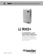
background image


RH2+


Installation and 

Operation Manual 

Includes installation, operation 
maintenance and troubleshooting 
information for your RH2+ Electric 
Steam humidifier 


2568051-F| 28 OCT 2014 


Important: 

Read and save these instructions. This guide to be left with equipment owner. 


Summary of Contents for RH2

Page 1: ...n Manual Includes installation operation maintenance and troubleshooting information for your RH2 Electric Steam humidifier 2568051 F 28 OCT 2014 Important Read and save these instructions This guide to be left with equipment owner ...

Page 2: ...tten authorization of Nortec Humidity Ltd except to the extent required for installation or maintenance of recipient s equipment Liability Notice Nortec does not accept any liability for installations of humidity equipment installed by unqualified personnel or the use of parts components equipment that are not authorized or approved by Nortec Copyright Notice Copyright 2014 Nortec Humidity Ltd All...

Page 3: ...Check 25 On Off or Modulating Operation 26 Start Up Procedure 27 Nortec Digital Controls 28 RH2 Pre Start Up Checklist 31 Operation 32 LED Status Lights 32 Selecting a Relative Humidity Setpoint 33 Humidifier Components 34 Description of Components 35 Humidifier Schematic 36 How the Humidifier Works 38 Humidifier Configuration 40 Maintenance and Servicing 41 Required Maintenance 45 Extended Shutdo...

Page 4: ...to local and national electrical code Electrical connection to be performed by a licensed electrician CAUTION Plumbing Plumbing to be performed by a licensed plumber Drain water from humidifier can be very hot Do not drain to public sink All plumbing work should be done according to local plumbing code CAUTION Installation Do not mount on hot surfaces Do not mount in area where freezing can occur ...

Page 5: ...re that available voltage and phase corresponds with humidifier voltage and phase as indicated on humidifier s specification label 2 Ensure that the dedicated external fuse disconnect is of sufficient size to handle the rated amps as indicated on the specification label Refer to local codes 3 Report any discrepancy immediately to the site engineer if applicable 4 Ensure sufficient clearances will ...

Page 6: ...n to a remote blower pack The space model is designed for applications where humidity is to be introduced directly into the conditioned environment The two models can be differentiated by the grille in the humidifiers front cover see Figure 2 RH2 Models Figure 2 RH2 Models Table 1 RH2 Specifications Model Part No Volts Capacity lb kg KW Amps Phase Max Ext Fuse Standard Cylinder Net Full Weight lb ...

Page 7: ...ion Table 2 Options and Accessories Option Accessory Application Steam Distributors Introducing steam into ventilation ducts Remote Blower Pack Introducing steam into conditioned environments Digital or Modulating Control Humidistats Controlling the output of the humidifier based on sensed RH Digital or Modulating High Limit Humidistats Preventing over humidification in a duct by shutting down or ...

Page 8: ... Condensate Returns 16 Electrical 17 External Controls 17 Control Wiring 17 Duct Humidification Control Location 18 Space Humidification Control Location 19 On Off Control Wiring 20 Modulating Control Wiring 21 Fan Enable Wiring 21 RH2 Fan Control 21 Nortec On Off Humidistat Fan Control 22 Options and Accessories 22 Remote Blower Pack ...

Page 9: ...Installation 6 Typical RH2 Installation Figure 3 Typical Humidifier Installation 2 ...

Page 10: ... any further then absolutely necessary from the steam distributor location as net output will be reduced as a result of heat loss through the steam line When possible mount the RH2 humidifier at a height convenient for servicing Figure 4 Mounting Location Clearance Side clearance for space models only see table 36 in 92 cm in ront learance duct model m f c Additional front clearance for space mode...

Page 11: ...t 1 4 in 6 mm is exposed Raise the unit and place the screw head through the keyhole 4 Make sure the unit is level and then insert and tighten the second screw through the bottom hole Tighten the top screw See Figure 5 Mounting With Keyholes Figure 5 Mounting With Keyholes Note Use screws longer than 2 5 cm if drywall or other spacer is present Install Second Screw after hanging humidifier 8 x 2 i...

Page 12: ...clamp Always install a water shut off valve 1 8 in NPT Use 1 4 in compression fitting to connect supply line to unit Pipe and water shut off valve not supplied by Nortec Use 1 2 in OD copper to within 4 ft 1 2 m of humidifier Note 1 Fill and drain lines can also be routed through opening in back of cabinet 2 Optional cover 2548313 Is available to conceal plumbing connections Air gap required 2 1 2...

Page 13: ...Includes a steam distributor steam hose condensate hose and installation hardware See Figure 8 Select to duct dimensions ASD Duct Distributor Used when duct width exceeds 12 Refer to Distributor manual or HELP software for selection Select to duct dimensions Mini SAM e Used when short absorption is necessary Refer to SAM e manual or HELP software for selection 2564776 RMBP for RH2 Duct Remote Moun...

Page 14: ...11 Installation Figure 7 RH2 Duct Nozzle Distributor Installation Figure 8 RH2 Duct RSD10 Distributor Installation ...

Page 15: ... 0 7 Oversized Steam Line used for longer steam runs 110 120V Not Recommended Not Recommended 1 1 125 X 0 049W Not Recommended 208V 8 7 3 3 12 3 5 2 0 9 220 240V 10 4 6 24 7 3 1 4 Note The use of steam line other than copper stainless steel tube or Nortec supplied steam line will void the warranty and may adversely affect the operation of the humidifier These diameters require a reducer at humidif...

Page 16: ... for Traps Do not over tighten hose clamp at cylinder steam outlet The maximum torque is 12 in lbs Support steam line so weight is not on cylinder Condensate traps must be a minimum of 6 in 15 cm in height or duct static pressure 2 in 5 cm whichever is greater Trapping by P trap or pigtail Support line as necessary to ensure it remains free of kinks Steam Direction Steam Direction Steam Direction ...

Page 17: ...30 cm min Before any bend Min 12 in 30 cm radius Hose will soften over time proper support Is necessary Support Brackets 1 ft 30 cm min To Drain 1 ft 30 cm min before any bend 12 in 30 cm min Radius Condensate Trap Condensate line Connect Steam Hose to Cylinder Connect Condensate Hose to Fill Cup 2 in 5 cm min 1 ft 30 cm Support Brackets ...

Page 18: ...ap at vertical transition Condensate trap not 12 in 30 cm below distributor 1ft 30 cm min before any bend 12 in 30 cm min radius Obstruction Use full size condensate tee at low point Slope lines up to T and immediately after it Hose will soften over time proper support Is necessary Support brackets 1 ft 30 cm min To drain To drain 2 in 5 cm min 1 ft 30 cm ...

Page 19: ...Installation 16 Electrical Figure 15 Primary Power Connection Caution Wiring to be performed by a licensed Electrician ...

Page 20: ...ct Humidification Duct Humidification Control Location 1 Air Proving Switch o Locate upstream so that it can sense air flow or lack of it 2 Duct High Limit Can be modulating or On Off humidistat o Locate at least 10 feet downstream from steam distributor or far enough that under normal conditions steam is fully absorbed 3 Humidity Control Can be Modulating or On Off humidistat o Can be located eit...

Page 21: ...oom humidity draft doorways sunlight or overhang such as a shelf can affect reading 2 High Limit Humidistat not shown o Install an On Off High Limit Humidistat in an area representative of room humidity 3 Outdoor Temperature Sensor not shown o Mount outside in area representing air temperature Note Regardless of selecting on off or modulating control method Nortec humidifiers must have a closed ci...

Page 22: ...19 Installation On Off Control Wiring Figure 18 On Off Controls Figure 19 Digital On Off Humidistat ...

Page 23: ...Installation 20 Modulating Control Wiring Figure 20 Modulating Controls Figure 21 Modulating Control Wiring ...

Page 24: ...l for exact wiring instructions on how to enable the fan RH2 Fan Control The RH2 can be used to turn on a furnace fan where there is a demand for humidity without a call for heat Humidifier will not start producing steam until fan security loop is closed Nortec On Off Humidistat Fan Control Nortec digital On Off humdistats include a second dry set of points to enable a fan where there is a call fo...

Page 25: ...remote blower pack refer to the installation instructions supplied with it The steam line instructions in this manual are also applicable to remote mounted blower packs except the slope must be larger because the blower pack does not have a separate condensate line and the maximum allowable steam line length is 4 ft 1 2 m Figure 24 Remote Mounted Blower Pack Note The blower pack requires additiona...

Page 26: ...23 Start Up Start Up 24 Installation Check 25 On Off or Modulating Operation 26 Start Up Procedure 27 Nortec Digital Controls 27 Modulating Control 27 On Off Control 28 RH2 Pre Start Up Checklist ...

Page 27: ...tion Check Before turning on power to the RH2 inspect the installation to ensure that it was carried out correctly Refer to RH2 Pre Start Up Checklist on page 28 and to the Installation chapter Figure 25 Installation Check ...

Page 28: ...inal 2 through an On Off humidistat and other security devices in series See On Off or Modulating Control J10 on page 39 for instructions on configuring the RH2 to operate as a modulating humidifier Caution Do not leave the On Off Drain switch in the drain position for extended periods of time The drain valve solenoid may heat up and result in damage to the valve and its wiring ...

Page 29: ...distat 8 When the external humidistat generates a demand for humidity and the security loop is closed the green humidifying LED on the front of the humidifier will light up the power relay on the control board will engage the fill valve will activate after a delay and the cylinder will slowly fill with water 9 If the fan enable relay is used the green LED will continue to flash until the air provi...

Page 30: ...se a PI control algorithm to open and close a relay that opens and closes the humidifier s On Off loop Adjust the setpoint to the desired setting by using the up down arrow buttons on the controller Output signal is shown on modulating controller proportional to the demand State of On Off humidistat Setpoint RH Humidity RH Indicates the humidistat is on A half moon indicates it is off Snowflake in...

Page 31: ... duct press 2in P Trap min 12 in drop WATER LINE 1 2 in to within 4ft of unit Water pressure 30 80 psig Cold water source 34 68ºF 1 20ºC DRAIN LINE Air gap within 3 ft of the unit Diameter Size CYLINDER Seated in drain valve yes no Torque for gear clamp of cylinder steam exit to steam line max 12 in lbs ______________ WIRING Wiring connections and connectors secured yes no CONTROLS On Off Security...

Page 32: ...itch on yes no On Off security loop Terminal 1 and 2 closed yes no Fan security Terminal 1 and 8 closed yes no CONTROLS Installed controls match configuration yes no Control Setpoint High Limit Setpoint 3 VDC on terminal 4 Modulating Humidistat yes no or Terminal 1 and 2 closed On Off Humidistat yes no The Humidifier will undergo a self test when the power is turned on activating the LED s and oth...

Page 33: ...Start Up 30 ...

Page 34: ...ting a Relative Humidity Setpoint 33 Humidifier Components 34 Description of Components 35 Humidifier Schematic 36 How the Humidifier Works 36 Steam Generation 36 Drains 36 Steam Distribution 37 Steam Line 37 Condensate Return 38 Humidifier Configuration ...

Page 35: ... a conditioned environment to prevent build up of condensation on the inside of exterior walls windows and trim It is highly recommended that the temperature setback function of the Nortec Digital controls be used under these conditions to prevent damage from condensation The digital control with an outdoor temperature sensor installed will automatically setback the humidity setpoint to correspond...

Page 36: ...fier Components Steam Outlet Condensate Return Fill Cup Drain Valve Drain Canal Fill Valve Cylinder Cylinder Plug High Water Sensor Plug On Off Drain Switch Control Board Power Relay High Voltage Terminal Block Transformer Control Terminal Strip Blowerpack ...

Page 37: ...from humidifier Control Board Controls all functions of the humidifier operation and provides input and output connections to humidifier components Fill Cup Provides an air gap for backflow prevention Fill Valve Controls flow of water into humidifier High Voltage Terminal Block Primary power connection from remote disconnect to humidifier High Water sensor Plug Used to detect max water level in cy...

Page 38: ...35 Operation Humidifier Schematic Figure 29 Humidifier Schematic ...

Page 39: ...down cycle repeatedly to match output to demand Over time minerals in the water will adhere to the cylinder electrodes The humidifier will automatically fill to a higher water level to maintain full capacity during the life of the cylinder Eventually because of scale formation it will no longer be possible for the humidifier to reach its full capacity The RH2 software monitors this condition and w...

Page 40: ...Return Whenever steam is distributed condensate is formed in the distribution system Insulating steam lines is one important way to reduce the amount of condensate formed Steam lines are sloped so that condensate does not collect in the lines and create a restriction to steam flow The condensate must be collected and removed from the system so that it does not build up and leak into the duct or ro...

Page 41: ...umpers and the capacity adjustment potentiometer Note Nortec recommends not making any configuration changes unless they are required and that any changes to the RH2 settings be performed by a qualified technician Figure 31 RH2 Control Board Jumpers Capacity Adjustment The capacity adjustment potentiometer can adjust the capacity of the humidifier between 100 and 30 of its rated output Factory set...

Page 42: ...jumper 13 Factory setting Jumper Removed 0 10 VDC or 0 20 mA control signal J13 Removed Controller is configured for a 0 10 VDC or 0 20 mA control signal J13 Installed Controller is configured for a 2 10 VDC or 4 20 mA control signal For mA control a 500 register is required between terminals 3 and 4 on the low voltage control terminal Table 6 Control Jumper Configuration Resulting Control J10 J13...

Page 43: ...g 41 Required Maintenance 41 Cylinder Spent Fault 41 Replacement Cylinder 42 Removing the Cylinder 43 Drain Valve Cleaning 44 Installing the New Cylinder 45 Extended Shutdown 45 Starting After Extended Shutdown 46 RH2 Maintenance Checklist ...

Page 44: ...nder life is dependent on water supply conditions and humidifier usage Replacement Cylinder The label on the existing cylinder identifies the cylinder type in its top left corner When ordering a cylinder always quote the three or five digit model number on the label the humidifier s serial number and the humidifiers voltage Serial number and voltage are located on the specification label on the le...

Page 45: ...from the cylinder pins by pulling vertically 7 Using a flat screwdriver loosen the hose clamp where the hose is connected to the cylinder 8 Tip the top of the cylinder forward to pivot it out of the steam hose When free of steam hose lift the cylinder out Figure 34 Cylinder Removal Warning Disconnect main power at the external disconnect before any servicing The inside of the humidifier cabinet co...

Page 46: ...ft the drain valve from the drain pan 4 Unsnap red coil cap on solenoid and remove the solenoid from the valve 5 Loosen brass nut holding actuator to plastic housing with a wrench and disassemble actuator 6 Clean actuator components and valve housing inlet port outlet port and cylinder port Put new o ring that was supplied with new cylinder into valve 7 Reassemble actuator making sure tapered end ...

Page 47: ...responding color coded cylinder pin Push down completely Connect high water sensor plug Spring loaded plugs should fit snuggly onto the cylinder pin Replace if they are loose or damaged 4 Replace the humidifier cover and secure with two screws 5 Turn on power to humidifier with the external disconnect 6 Open supply water shut off valve 7 Turn the humidifier On Off Drain switch to On Sleeve and Sol...

Page 48: ...d Refer to the Chapter on Start Up 2 Turn on the power to the humidifier with the external disconnect 3 Turn the On Off Drain switch to the Drain position 4 Wait until there is no water flowing to drain It usually takes less than 10 minutes 5 Follow the start up procedure in the chapter on Start Up Note As long as the RH2 is powered it will automatically drain the cylinder when there has not been ...

Page 49: ...w Cylinder Installed New cylinder model Should be same as removed cylinder Cylinder plug colors match cylinder dots Cylinder plugs snug and in good condition High Water Sensor plug snug and in good condition Cover replaced water shut off valve open On Off Drain switch On Disconnect Closed SYSTEM CHECK Yellow Led flashing No Yes Flash Sequence See Troubleshooting Chapter for actions if yellow LED i...

Page 50: ...g Chapter 48 Troubleshooting Requirements 49 General Troubleshooting 49 Humidifier 50 Steam Distributors 50 Blower Pack 50 Digital Humidistat 51 RH2 Faults 51 LED Flash Sequence 51 Clearing a Fault 53 RH2 Wiring Diagram 54 Exploded View and Spare Parts List 58 Warranty ...

Page 51: ...nstalled on the inside of the humidifier door A generic copy of the RH2 wiring diagram is also included at the end of this chapter for reference purposes When contacting your local representative or Nortec for troubleshooting assistance please ensure the serial number has been obtained for reference purposes NOTE Most humidifier faults are not caused by faulty equipment but rather by improper inst...

Page 52: ...2 1c Check jumper is installed in air proving safety loop terminal 1 and 8 2 No demand signal 2 Check voltage between terminal 3 and 4 For demand configuration 35 of full scale signal must be present for humidifier to start 3 Not configured correctly for On Off or modulating control 3 Check that J10 on control board is removed for modulating control and installed for On Off control 4 Capacity has ...

Page 53: ...as been installed with condensate traps and slope per installation instructions on page 12 Condensation in duct 1 Installation clearances not observed 1 Refer to distributor installation manual for required clearances Relocate distributor if required 2 Design conditions changed 2 Check supply air temperature and humidity to determine if conditions have changed 3 High limit not functioning 3 Check ...

Page 54: ...learing the fault Table 8 Troubleshooting RH2 Faults Yellow LED System Detected Cause Corrective Action s 1 flash Excess Current Current has exceeded 130 of max 1 Drain blocked water over concentrated 1 Clean the drain line 2 Drain solenoid not energized water over concentrated 2 Check and correct wiring to drain valve 3 Filling too fast fill valve damaged and leaking 3 Replace the fill valve 4 Fi...

Page 55: ...pplied to unit not treated water RO or DI 6b Check conductivity of water If less than 150 µS cm 6c Add 1 4 teaspoon of salt to fill cup and restart unit 3 flashes No Current High Water Water level at top of cylinder with no current 1 Primary wire not looped through current transformer 1 Open disconnect rewire primary wire through current transformer 2 High water sensor plug is on an electrode pin ...

Page 56: ...53 Troubleshooting RH2 Wiring Diagram ...

Page 57: ...tion 2560953 RH2 Duct 10lbs hr 120 208 240V 1P 2560952 RH2 Space 8lbs hr 120 208 240V 1P Spare parts RH and RH2 models can be found in RH2 manual 2549509 Go to www humidity com to download RH2 manual 2549509 tNortec Part No Description 2548759 RH Duct 10lbs hr 120 208 240V 1P 2548758 RH Space 8lbs hr 120 208 240V 1P 2548005 RH2 Duct 10lbs hr 120 208 240V 1P 2548004 RH2 Space 8lbs hr 120 208 240V 1...

Page 58: ...Parts RH2 Spare Parts The following spares parts are for RH2 models only tNortec Part No Description 2560953 RH2 Duct 10lbs hr 120 208 240V 1P 2560952 RH2 Space 8lbs hr 120 208 240V 1P Figure 37 RH2 Spare parts ...

Page 59: ...und Clamp 5 2548008 RH2 SPACE Power Supply 6 2548314 RH2 SPACE Fan 7 2548683 RH2 SPACE Distributor 8 2573515 Fill Valve 9 2568368 RH2 SPACE Condensate Hose 10 1456000 Drain Valve Assembly 11 2548313 Optional Bottom Cover 12 2562415 Transformer Multi tap 120 208 240V 13 2547964 Cylinder Plug Kit 14 1639011 Elbow Compression Fitting Assembly 15 2568048 or 2568047 PCB RH2 DUCT10 lbs hr or PCB RH2 SPA...

Page 60: ...57 Spare Parts ...

Page 61: ... shall be attached to THE COMPANY until said products have been paid for in full and then said liability shall be limited to the original purchase price for the product Any further warranty must be in writing signed by an officer of THE COMPANY THE COMPANY s limited warranty on accessories not of the companies manufacture such as controls humidistats pumps etc is limited to the warranty of the ori...

Page 62: ...U S A 1860 Renaissance Blvd Sturtevant WI 53177 826 Proctor Avenue Ogdensburg NY 13669 CANADA 2740 Fenton Road Ottawa Ontario K1T 3T7 TEL 1 866 NORTEC1 EMAIL nortec humidity com WEBSITE www humidity com ...

Reviews: