background image

MM571W / MM572W Installation Instructions

32

CONNECTING THE OPERATOR(S) AND BATTERY 

GRN

WHT

BAT+

RESET

BAT–

GRN

WHT

RED

BLU

RED

BLU

COM

COM

AUX  V+ AUX  V-

LOCK  V+ LOCK V-

PRIMAR

Y

SECONDAR

Y

LOCK

AUX

SW1
SW2

SECURE SEALING NUT

B

SEALING NUT


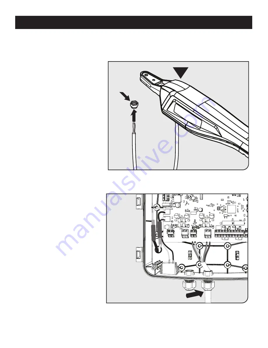
Remove the sealing nut from one of 
the cable glands on the bottom of the 
control box.


Feed the operator wiring harness 
through the sealing nut.


For 572W, repeat for the SECONDARY 
operator.


Insert the wire harness through the 
cable gland into the control box at 
least 3” to allow connection to the 
operator wiring terminals.


Secure the cable in place by 
tightening the sealing nut.


For 572W, repeat for the SECONDARY 
operator.

Step 1

Step 2

Summary of Contents for Mighty Mule MM571W

Page 1: ...it not included to run second opener power cable under driveway Gate Bracket Warning Sign Secondary Opener Primary Gate Opener Horizontal Support Post Bracket Gate Bracket Warning Sign Control Box mou...

Page 2: ...WARNING DO NOT SPLICE ANY POWER WIRES DO NOT MODIFY THE BATTERY HARNESS THIS WILL VOID YOUR MANUFACTURER S WARRANTY Low voltage wire for transformer not included...

Page 3: ...ded to service the general public Vehicular Gate Operator Class Categories WARNING This equipment meets Underwriters Laboratory Standard 325 UL 325 However gate equipment has hazards associated with i...

Page 4: ...ing Most Common 16 Installing the Closed Position Stop Plate Pull to Open 21 Push to Open Operator Mounting 24 Installing the Closed Position Stop Plate Push to Open 29 Control Box Installation 30 Con...

Page 5: ...e gates due to the potential to damage the operator and or injure someone The Mighty Mule Gate Operator accommodates extra transmitters digital keypads solar panels push buttons automatic gate locks a...

Page 6: ...x power switch OFF 2 Remove the hairpin clip and clevis pin 3 Remove the operator s front mount from the gate bracket The gate can be opened and closed manually when the operator is disconnected manua...

Page 7: ...ake sure the gate system is placed far enough from the road to prevent traffic congestion FOR THE INSTALLER AND END USER Gate in the Open Position ZONE 2 ZONE 3 ZONE 4 ZONE 5 Driveway ZONE 1 Entrapmen...

Page 8: ...will be tempted to reach through the gate to activate the gate operator 5 Secure outdoor or easily accessed gate operator controls in order to prohibit unauthorized use of the gate FOR THE INSTALLER...

Page 9: ...wer to operator OFF before performing any maintenance See page 48 for maintenance procedures 7 To operate this equipment safely YOU must know how to disconnect the operator for manual gate operation s...

Page 10: ...ing Edges of gates Gate Warning Sign Gate Warning Sign Control Box Leading Edge of the gate Photo Beam recommended not included Photo Beam recommended not included Sensing Edges recommended not includ...

Page 11: ...eparate access opening The pedestrian access opening shall be designed to promote pedestrian usage Locate the gate such that persons will not come in contact with the vehicular gate during the entire...

Page 12: ...d placer tout moment 2 Lisez toutes les instructions de s curit dans le manuel de l utilisateur 3 Ne laissez pas les enfants utiliser la barri re ou jouer proximit de la barri re 4 Cette barri re est...

Page 13: ...prevents battery discharge IMPORTANT Never use both transformer and solar panel this will damage the battery and control board Three 3 Mini blade style fuses rated for 25A NOTE The transformer should...

Page 14: ...the control board The table and map illustrate the maximum number of gate cycles to expect per day in a particular area when using from 10 to 30 watts of solar charging power prior to the battery dep...

Page 15: ...Make sure there is a stable area for mounting the gate bracket this may require the addition of a horizontal or vertical cross member We recommend you position the operator near the center line of a...

Page 16: ...8 Nut 7 5 16 Lock Nut 1 U T 5 16 x 1 1 2 Bolt 1 Q W P 3 8 x 2 3 4 Bolt 2 3 8 Lock Washer 7 V 3 8 x 1 1 2 Bolt 1 Hairpin Clip 2 10 14 x 3 4 Screw 8 N O 3 8 x 1 1 2 Clevis Pin 2 3 8 x 8 Bolt 4 8 Nylon C...

Page 17: ...einforcing Gates for the Gate Brackets next page Depending on the type of gate a horizontal cross member or mounting plate may be needed to mount the front of the operator and gate bracket to the gate...

Page 18: ...commend using a muffler clamp wood or metal to reinforce thin walled tube gates or wood to reinforce panel gates as shown These reinforcement methods will prevent damage to the opener and gate Additio...

Page 19: ...R MOUNTING MOST COMMON Assemble the gate post bracket sub assembly as displayed Attach the gate post bracket subassembly and gate bracket to the operator as shown The operator must be retracted with t...

Page 20: ...e stress on the operator and may cause physical damage and or strain the motor TIP Turning the pivot bracket over gives more hole alignment options for the gate post pivot bracket assembly With the ga...

Page 21: ...g locations for the gate bracket Open the gate and reattach the operator to the gate bracket Ensure that the operator arm is level and the brackets are securely clamped Secure the post pivot bracket i...

Page 22: ...ING Using a drill and 7 16 drill bit drill the necessary holes to mount the gate post and gate brackets Note Some installations may require additional reinforcement be installed on the gate See page 1...

Page 23: ...e side near the control box Install the secondary operator on the remaining leaf by repeating the same process illustrated in steps 1 11 above Note You will need to run the secondary operator power ca...

Page 24: ...e closed position and adjust the closed position stop plate against the fence post Tighten the mounting hardware Return the gate to the open position and reinstall the operator arm To complete the pul...

Page 25: ...systems install the Ground Stop Plates on the inside of the gates For Push to Open systems install the Ground Stop Plates on the outside of the gates Step 1 Detach the gate opener arms from the gates...

Page 26: ...tach the vertical closed position stop plate to the SECOND gate frame at the point where it will come in contact with the low profile ground stop Do not tighten it completely at this time You must sli...

Page 27: ...te post bracket subassembly as shown with the Push to Open pivot bracket FM148 Must be purchased separately Attach the gate post bracket subassembly and gate bracket to the operator as shown The opera...

Page 28: ...learance between the operator arm and gate See illustration in Step 4 below 20 MAX CLEARANCE DIAGRAM Disconnect the operator arm from the gate bracket While supporting the operator swing the gate and...

Page 29: ...et subassembly Remove the operator arm from the gate post and gate brackets Mark the center of the mounting locations for the gate bracket PUSH TO OPEN OPERATOR MOUNTING Step 6 Step 5 Step 7 Q K U Clo...

Page 30: ...ure the gate post bracket subassembly with the supplied hardware as shown Using a drill and 7 16 drill bit drill the necessary holes to mount the gate post and gate brackets Note Some installations ma...

Page 31: ...as shown Once the gate post and gate brackets are installed reattach the operator arm Ensure the operator arm is level adjusting the post bracket location if necessary Once level ensure all hardware...

Page 32: ...e next step INSTALLING THE CLOSED POSITION STOP PLATE PUSH TO OPEN H 1 1 2 Step 1 Step 2 Swing the gate to the closed position and adjust the closed position stop plate against the fence post Tighten...

Page 33: ...nd the metal post requiring additional hardware not supplied Connect the battery harness to the battery as shown red to positive black to negative terminals Place the battery into the right side of th...

Page 34: ...knock out the battery cable access hole in the panel Feed the battery cables through the control board casing access hole Attach the control board casing using the eight screws provided NOTE Figure do...

Page 35: ...emove the sealing nut from one of the cable glands on the bottom of the control box Feed the operator wiring harness through the sealing nut For 572W repeat for the SECONDARY operator Insert the wire...

Page 36: ...m the SECONDARY operator Tighten the screw terminals ensuring the wires are captured correctly as shown Step 3 Step 4 GRN WHT BAT AUTO CLOSE RESET PULL STAGGER WARNING BAT GRN WHT RED BLK RED BLK COM...

Page 37: ...lling a solar panel FM123 sold separately see solar panel instruction manual and skip to Step 3 Note If your outlet is outside you must use a weatherproof cover Along the identified path between outle...

Page 38: ...l wires into the control box using one of the access locations on the bottom of the box Connect the RED wire to PWR and the BLACK wire to PWR on TERM 6 as shown Step 3 Step 3B MM572 Only Cut a 6 deep...

Page 39: ...V LOCK V LOCK V CLOSE EDGE OPEN EDGE PRIMARY SECONDARY LOCK AUX PUSH 1 2 3 4 5 GRN WHT BAT BAT GRN WHT BRN ORG RED BLK RED BLK AUX V AUX V PRIMARY SECONDARY SW1 SW2 TERM6 ery Power Access SW1 SW1 From...

Page 40: ...and closing for compatibility with gate locks 3 Warning The WARNING DIP switch toggles a movement alarm ON or OFF Powering the System Locate the ON OFF switch on the bottom left of the control box To...

Page 41: ...itters or Keypad codes 1 Enter the Learn Transmitter mode following step 1 above 2 Press and hold the down arrow button until LED1 2 3 flash and the buzzer sounds Approximately 10 seconds Note The con...

Page 42: ...n Applications Step 1 Enter the primary arm limit programming mode With the power on for your control box press and hold both the S2 and the S3 buttons at the same time until LED 1 turns on and the bu...

Page 43: ...2 and you will hear a long beep and the arm will begin to extend closing the gate Continue holding the button down until the gate reaches the desired closed position and then release 5 If you overshoo...

Page 44: ...en Applications Step 1 Enter the primary arm limit programming mode With the power on for your control box press and hold both the S2 and the S3 buttons at the same time until LED 1 turns on and the b...

Page 45: ...2 and you should hear a long beep and the arm will begin to extend opening the gate Keep holding the button down until the gate reaches the desired open position and then release 5 If you overshoot th...

Page 46: ...ion The controller includes three Stall Force settings and is preset from the factory to Low If your operator stops and reverses during a normal cycle follow the instructions below to change the Stall...

Page 47: ...to OFF from the factory To set an auto close timer use a small flat head screw driver to turn the auto close potentiometer clockwise The timer can be set from approximately 3 seconds to a maximum of 1...

Page 48: ...however we do not endorse any specific brand names Only use products that are listed to be in compliance with any applicable UL safety standards and national and regional codes PLEASE NOTE Contact sen...

Page 49: ...ill prevent gate from closing 6 EDGE Typically for use with contact edge sensor Activation of this input while gate is moving will cause it to reverse direction for 2 seconds Activation of this input...

Page 50: ...r is required between LOCK V and LOCK Relay Common Mighty Mule Push Button Control NOTE Connections are for typical applications For additional connection options not illustrated here refer to the acc...

Page 51: ...Monthly turn off the power switch and disconnect the Mighty Mule and move the gate to make sure the gate is moving freely without sticking or binding Lubricate the hinges or repair the gate as require...

Page 52: ...Battery harness connections h Battery under load or inadequate charge 1 beep pause 1 beep Open circuit Primary arm h Primary arm connections white and green h Arm power cable 2 beeps pause 2 beeps Ope...

Page 53: ...rol board problem 1 beep pause 3 beeps pause 1 beep pause 3 beeps pause Reading secondary motor short condition h Turn the system off and back on h Motor leads shorted h Internal arm problem or contro...

Page 54: ...oubleshoot each accessory that was removed and associated wiring individually LED 2 red 2 blinks pause 2 blinks Safety SAFE terminal shorted LED 2 red 3 blinks pause 3 blinks Exit EXIT terminal shorte...

Page 55: ...a triggered stuck transmitter or accessory by removing batteries from all other wireless accessories The unit reverses before completing an open or close Gate unit has sensed an obstruction h Path of...

Page 56: ...outside of the package in LARGE BOLD PRINT Ship the package s freight prepaid to the address provided during the RA process If your Mighty Mule Gate Opener is not operating properly please follow the...

Page 57: ...xits the property 100 ft range between transmitter and receiver Easy installation Wireless Connectivity System MMS100 Adds smart functionality to your gate operator utilizing the Mighty Mule App PAIR...

Page 58: ...B509 500 500 The 16 gauge stranded dual conductor Low Voltage Wire is for connecting the AC powered transformer or the Solar Panel to the control board Also used for the connection of accessories such...

Page 59: ...of the installation following the accessory instructions Notes 1 If you need to erase this device repeat steps 2 4 above 2 Erasing all transmitters on the gate operator control board will erase this d...

Page 60: ...otion The power switch must be turned off before using the manual disconnect and disengaging the operator 10 Reviewed all safety instructions and keep the safety instructions and owner s information s...

Reviews: