7
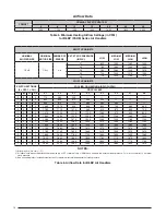
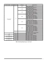
table 1. optional Accessory Kits
DEScRIptIoN
cABINEt SIZE
B
c
Downflow Plenum Connector, 6.25”
913840
914969
Downflow Plenum Connector, 8.25”
913841
914970
Downflow Plenum Connector, 10.25”
913842
914971
Upflow Pedestal Mounting Stand
913872
913873
Downflow Coil Adaptor
919321
919322
*919323
* Use when installing B width coil in C width cabinet
5. Remove the plenum connector and cut out the marked
area of the supply air duct.
NotE:
To allow some clearance for installing the plenum
connector, cut the opening 1/4” larger the actual cutout
drawn.
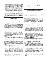
6. Install the duct connector back in the floor opening with
the bottom tabs extending into the supply air duct. See
.
7. Secure the plenum connector to the wood floor with
appropriate size screws.
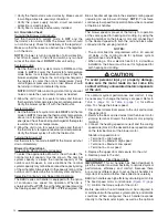
8. Bend the connector tabs on the bottom of the plenum
connector upwards and as tight as possible against the
supply air duct. See
.
9. Seal all connections with industrial grade sealing tape
or liquid sealant.
Requirements for sealing ductwork
vary from region to region. consult with local codes
for requirements specific to your area.
A/c or H/p coil Installation
Approved air conditioning and heat pump system
components are listed on the unit nameplate. To install
the indoor coil:
1. Remove door cover plate, door and coil close-off plate
(with insulation). Discard door cover plate.
2. Upflow Applications: Slide the coil into the track located
in the bottom of the unit.
Downflow Applications: The downflow adaptor must be
used. See
. Install the downflow adaptor and
coil as directed in the instructions supplied with the kit.
3. Reinstall the door and coil close-off plate (with insulation).
NotE:
In downflow applications the door is rotated 180°
so that the refrigerant and condensate lines remain on
the left side.
4. Install the refrigerant and condensate lines as directed
in the instructions supplied with the outdoor unit.
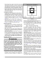
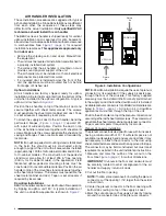
Figure 3. plenum Adapter
13.25"
18.5" (B-Cab.)
21.25" (C-Cab.)
Plenum
Connector
Connector
Tabs
Supply
Air Duct
Wood Floor
Duct Connector
Supply
Air Duct
Bend tabs tightly
against supply air duct
Figure 5. Duct connector Installed
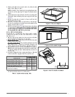
Figure 4. perforated Flanges
Summary of Contents for B6BV Series
Page 23: ...23...


