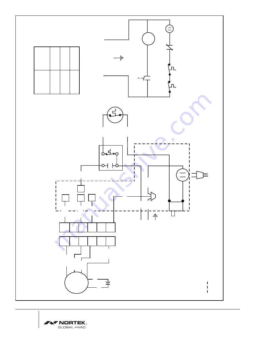
Burner Plug
Receptacle
Blower Speed Setting Shown
is the Medium Speed
(see table)
Fan & Limit
Control
Manual Sw.
Fan Sw.
If any of the original wire supplied
with the appliance is replaced, use
105 C wire or equivalent.
Limit
Sw.
Aux.
Sw.
Door
Sw.
Recpt.
Motor
Door
Switch
120V N
L1
G
Aux. Limit
Blk
Blk
L1
120V
G
N
1
2
3
4
5
6
1
2
3
4
5
6
1
1
1
1
Blue
Red
Blower Motor
Wht
Wht
Blk
Red
Blue
Blk
Wht
Wht
Blk
Red
Blower
Wire Color
Blower Speed
Blue
Black
Low
Med.
High
Represents Control Box
Blk
Brn
Brn
Blower Motor
Capacitor
CMF Wiring Diagram
067A-0298
Specifications and illustrations subject to change without notice
and without incurring obligations. Printed in U.S.A. (11/98)
O'Fallon
, MO
© Nortek Global HVAC LLC 2015. All Rights Reserved.


