12
Outdoor Terminations - Vertical Venting
Termination spacing requirements from the roof and from
. The roof penetration must
be properly flashed and waterproofed with a plumbing roof
boot or equivalent flashing. Vent and combustion air piping
may be installed in an existing chimney which is not in use
provided that:
• Both the exhaust vent and air intake run the length of the
chimney.
• The top of the chimney is sealed and weatherproofed.
• The termination clearances shown in
maintained.
• No other gas fired or fuel-burning equipment is vented
through the chimney.
Vent Freezing Protection
CAUTION:
When the vent pipe is exposed to temperatures
below freezing (i.e., when it passes through
unheated spaces, chimneys, etc.) the pipe
must be insulated with 1/2 inch thick sponge
rubber insulation, Armaflex-type insulation or
equivalent. Insulating pipe is important to avoid
condensate icing.
•
lists the maximum length of flue pipe that can
travel through an unconditioned space or an exterior
space. The total vent length must not exceed the lengths
noted in
. For Canadian installations,
please refer to the Canadian Installation Code (CAN/
CSA-B149.1 or 2) and/or local codes.
• For extremely cold climates or for conditions of short
furnace cycles (i.e. set back thermostat conditions)
the last 18 inches of vent pipe can be reduced. It is
acceptable to reduce from 3” to 2-1/2”, 3” to 2”, or 2” to
1-1/2” if the total vent length is at least 15 feet in length,
and the vent length is within the parameters specified in
. The restriction should be counted as 3 equivalent
feet. Smaller vent pipes are less susceptible to freezing,
but must not be excessively restrictive. The length of the
2 inch pipe must not be longer than 18 inches.
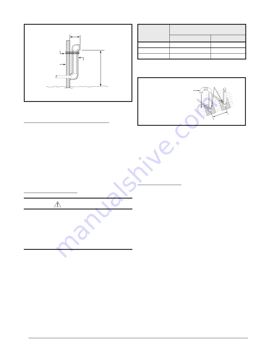
Figure 9. Alternate Horizontal Vent Installation
Support
NOTE:
Vent Configuration to Provide
12" Minimum height above Snow Level.
1/2"
Armaflex
Insulation or
Equivalent
(if required)
12" Above
Maximum
Expected
Snow Level
19" Max.
(See Note)
Outside
Wall
Figure 10. Vertical Vent Termination
Comb
ustion Air
Exhaust
V
ent
12” Above Maximum
Expected Snow Level
(Both pipes)
Elbows on the combustion air
inlet must be positioned pointing
away from the exhaust vent.
8" Min.
36" Max.
Plumbing Vent Roof Boot
(Both Pipes)
WINTER DESIGN
TEMPERATURE
MAXIMUM FLUE PIPE LENGTH (FEET)
IN UNCONDITIONED & EXTERIOR SPACES
WITHOUT INSULATION
WITH INSULATION*
20
45
70
0
20
70
-20
10
60
*NOTE:
Insulation thickness greater than 3/8 inch, based on an R value
of 3.5 (ft x F x hr) / (BTU x in.)
Table 2. Vent Protection
• If furnace is installed horiziontally, make sure the drainage
port on the in-line drain assembly is pointed downward to
ensure proper drainage of condensate. For *SC series,
see
• To prevent debris or creatures from entering the
combustion system, a protective screen may be installed
over the combustion air intake opening. The screens hole
size must be large enough to prevent air restriction.
Existing Installations
When an existing furnace is removed from a vent system
serving other appliances, the existing vent system may not be
sized properly to vent the remaining appliances (For example:
water heater). An improperly sized venting system can result
in the formation of condensate, leakage, or spillage. The
existing vent system should be checked to make sure it is in
compliance with NFGC and must be brought into compliance
before installing the furnace.
NOTE:
If replacing an existing furnace, it is possible you will
encounter an existing plastic venting system that is subject
to a Consumer Product Safety Commission recall. The pipes
involved in the recall are High Temperature Plastic Vent
(HTPV).
If your venting system contains these pipes
DO
NOT reuse this venting system!
This recall does not apply
to other plastic vent pipes, such as white PVC or CPVC.
Check for details on the CPSC website or call their toll-free
number (800) 758-3688.
Condensate Disposal
The method for disposing of condensate varies according
to local codes. Consult your local code or authority having
jurisdiction. Neutralizer kit is available for use with this furnace.
Refer to the technical sales literature for part numbers.
Please
follow the instructions provided with the kit
.
This furnace has multiple options for positioning the vent
pipe as described in the, Vent and Inducer Assembly Options
section (
). Each of the condensate drain lines must
be J-trapped using field supplied parts. After the condensate
lines are J-trapped, they may be combined together when
routed to the drain.


