background image

Reznor, PREEVA Neos, Installation Manual,  EN 2021-05, D301315 Iss 1    Page No 19 of 52 

I

Install a ground joint union and manual shut-off  
gas cock upstream of the unit control system. 

The unit is equipped with a nipple that extends 
outside the cabinet. 

Check that the gas category is in accordance 
with the data described on the air heater.

Ensure that a gas supply line includes a filter and 
has been tested and purged in accordance with 
prescribed practice prior to commissioning and 
taking the air heater into service.

This appliance is equipped for a maximum gas 
supply pressure of 50mbar.

Never use a flame to test for gas 
soundness.

PREEVA Neos units are designed to operate on 
natural gas (G20, G25 or G25.3). Check that the 
gas supply, gas category and gas inlet pressure 
is in accordance with the information given 
on the unit data plate. To let the unit function 
at maximal heat output, the gas supply pipe 
MUST be correctly sized. Close to the air heater 
a gas tap with coupling must be mounted for 
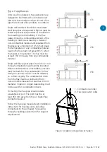
servicing (see figure 7). 

The whole of the gas service installation 
including the meter must be inspected, tested 
for soundness and purged in accordance with 
appropriate requirements by a qualified person.

Figure 7 Gas Connection Details

Open

Closed

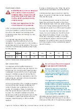
Table 4 Gas Supply Details

Country

Gas 

Category

Gas Type

Nominal 

Supply 

Pressure 

(mbar)

Maximum 

Supply 

Pressure 

(mbar)

Minimum 

Supply 

Pressure 

(mbar)

AT, BG, CH, CY, CZ, DK, EE, 

ES, FI, GB, GR, HR, IE, IT, LT, 

LV, NO, PT, RO, SE, SI, SK, TR

I

2H

Natural Gas (G20)

20

25

17

LU, PL, RO

I

2E

Natural Gas (G20)

20

25

17

BE

I

2E(R)B

Natural Gas (G20 / G25)

20 / 25

25 / 30

17 / 20

FR

I

2Er

Natural Gas (G20 / G25)

20 / 25

25 / 30

17 / 20

DE

I

2ELL

Natural Gas (G20 / G25)

20 / 20

25 / 30

17 / 18

NL

I

2EK

Natural Gas (G20 / G25.3)

20 / 25

25 / 30

17 / 20

Summary of Contents for PREEVA NEOS

Page 1: ...ation service or maintenance can cause property damage injury or death All work must be carried out by appropriately qualified persons The manufacturer does not take any responsibility in the event of...

Page 2: ......

Page 3: ...70 component layout 29 Model 100 component layout 30 Maintenance schedule 31 Heat exchanger maintenance 31 Replacement of gas valve 31 Venturi cleaning and replacement 32 Combustion fan cleaning and r...

Page 4: ...when failure to heed or implement the instruction s can lead to not only component damage but also to a hazardous situation being created where there is a risk of personal injury Warranty This equipm...

Page 5: ...l air intake complete with a water separator Important notice to installers Before installation carefully read these instructions and follow the processes explained by the manufacturer These instructi...

Page 6: ...pliance before shutting off the electrical supply Gas fired appliances are not designed for use in hazardous atmospheres containing flammable vapours or combustible dust in atmospheres containing chlo...

Page 7: ...booklet and become familiar with the installation requirements of your unit If you do not have knowledge of local requirements check with the gas supplier and any other local agencies who might have r...

Page 8: ...Flue Length m 9 5 Condensation Connection Outlet mm 22 Minimum Airflow at 15 C 5 m3 h 2000 2530 3060 3980 5300 8060 Temperature Rise at Minimum Airflow K 40 40 41 40 37 Maximum Airflow at 15 C 5 m3 h...

Page 9: ...10 205 205 210 H Outlet Opening mm 380 380 380 615 615 615 Optional Spigot for Outlet Opening mm 451 451 451 686 686 686 I mm 68 68 68 274 274 275 J mm 837 837 837 710 710 901 K mm 270 270 270 365 365...

Page 10: ...abinet mm 1584 1584 1584 1972 1972 2106 Q1 Lifting centres with filter cabinet mm 2604 2604 2604 3164 3164 3298 R mm 649 649 649 816 816 816 Please contact technical sales for dimensional data for uni...

Page 11: ...e the heater where it may be exposed to water or where the ambient temperature exceeds 40 C Suspension is not allowed when the air handler comprises more than a heating and ventilation section i e a m...

Page 12: ...be protected by a fence to guard against damage and to protect the public from possible injury Ensure that the structural elements which will be used to support the appliance are adequate to carry th...

Page 13: ...requirements If the appliance is installed in an area where extremely low external temperatures can occur measures will need to be taken to ensure frost protection is provided inside the burner contro...

Page 14: ...liance thus eliminating heat exchanger hot spots and nuisance shutdown of the burner due to over heating 1 Corner jointing framework Cut and assemble flange into frame to suit opening 2 Cleats between...

Page 15: ...the building Safe operation of any power vented gas apparatus requires a properly operating flue system correct provision for combustion air and regular maintenance and inspection The appliance must...

Page 16: ...ble test port The port must be at least 450mm away from the air heater flue connection socket Follow the flue pipe manufacturers installation instructions for making joints including connections to th...

Page 17: ...in operation The flue must be at least 150 mm away from any combustible material Single wall flue pipe exposed to cold air or run through unheated areas should be insulated Where condensation is unav...

Page 18: ...ion For external units it may be necessary to fit trace heating to the condensation pipe to prevent freezing Model PRN I 025 035 045 055 070 100 PRN E Condensate l hr 0 65 0 75 0 88 1 00 1 25 1 75 Tab...

Page 19: ...t pressure is in accordance with the information given on the unit data plate To let the unit function at maximal heat output the gas supply pipe MUST be correctly sized Close to the air heater a gas...

Page 20: ...on free surface and mounted about 1 5 metres above floor level Follow the thermostat manufacturers instructions The thermostat must be suitable for potential free contacts Electrical supply and connec...

Page 21: ...within 1 metre of the appliance 3 Phase Permanent Mains Supply L1 L3 Option on 25 35 models only Legend Heater Terminals Control Terminals Notes 1 Retain insert link wires shown solid 2 Terminals show...

Page 22: ...L2 and L3 and earth ground Verify that the appliance is earthed by conducting an earth continuity test Ensure that fuses are of the correct rating and fuse value Check ignition controller program key...

Page 23: ...um as shown on the data plate check the supply pipework to ensure it is correctly sized Gas pressure should be checked with the appliance running at maximum heat load When overheating occurs shut the...

Page 24: ...alues should be compared to those shown in the Combustion Data Table 1 Slacken screw in gas valve inlet pressure test point and attach gas pressure gauge 2 Start the appliance following the start up p...

Page 25: ...heat demand and allow heater to shut down Reconnect thermostat connections if bypassed for commissioning Commissioning hand over Upon full and satisfactory completion of commissioning a record of comm...

Page 26: ...G25 ppm 2 2 3 3 2 2 Low Fire Offset Pressure G25 Pa 15 14 37 43 78 1 3 CO2 at High Fire Throttle G25 3 8 70 8 59 8 65 8 78 8 73 8 56 CO G25 3 ppm 3 3 2 3 3 3 Throttle Turns from G20 1 9 out 2 5 out 1...

Page 27: ...e place If after three ignition attempts the burner does not relight safety shut down and lockout will occur Manual intervention to reset will be necessary to put the unit back into service In the eve...

Page 28: ...een the gas valve being energised and the flame sensor checking for the presence of a flame This is a period of 4 seconds Note if no flame is sensed the burner controller will attempt ignition 3 times...

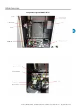
Page 29: ...No 29 of 52 MS Maintenance Component Layout Model 25 70 Gas Valve Combustion fan Venturi Enlarged view LC1 and LC3 safety thermostat bracket Union LC3 safety thermostat reset under cover Ignition tra...

Page 30: ...Manual EN 2021 05 D301315 Iss 1 MS Component Layout Model 100 Gas valve assembly see enlarged view Control assembly see enlarged view Combustion fan Venturi Gas Valve Ignition transformer Lockout res...

Page 31: ...for security and worthiness of the suspension or mounting system The following procedures should be carried out at least once each year see Figure 16 Clean all dirt lint and grease from the fan and mo...

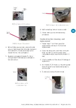
Page 32: ...screws 6 off Fixing screws 4 off Fixing screws 6 The gas supply pipe with flange can be removed by unscrewing the 4 fixings Do not lose the o ring seal PREEVA Neos 10 70 gas valve inlet flange assembl...

Page 33: ...crew Gasket PREEVA Neos 10 70 combustion fan O ring PREEVA Neos 100 combustion fan 6 Refit remaining items in reverse order 7 Follow start up and commissioning procedure Combustion fan cleaning and re...

Page 34: ...of clean water The burner should be allowed to dry naturally or be blown dry using compressed air drying air should not exceed 1 5 bar 7 Replace the burner gasket if necessary 8 Refit in reverse order...

Page 35: ...on the lower right side of the chamber where the probes are normally located It is recommended that both of these thin insulation strips are replaced whenever the cast insulation block is removed Ensu...

Page 36: ...Review the condition of the probes Light oxidation can be removed with a fine abrasive paper 7 Measure the length of each probe and check against the dimensions given below If probes are corroded or d...

Page 37: ...hdraw mounting bracket from heater 5 The thermostats can now be removed from the mounting bracket 6 Replace one or both thermostats as needed Ensure sensor is pushed up to the return at the end of the...

Page 38: ...circulation fan 1 Remove electrical terminal cover and disconnect cables 2 Loosen cable gland and retract cable 3 Disconnect flexible duct between fan inlet and appliance case 4 Unscrew fixings secur...

Page 39: ...2021 05 D301315 Iss 1 Page No 39 of 52 MS Unit operation The combustion and correct operation of the appliance should be verified as a part of the normal service routine Follow the steps in the start...

Page 40: ...Page No 40 of 52 Reznor PREEVA Neos Installation Manual EN 2021 05 D301315 Iss 1 FF Fault Finding...

Page 41: ...Reznor PREEVA Neos Installation Manual EN 2021 05 D301315 Iss 1 Page No 41 of 52 FF...

Page 42: ...sket and 2x fixing screws 03 25700 002 035 Venturi with gasket and 2x fixing screws 03 25700 001 045 Venturi with gasket and 2x fixing screws 03 25700 051 055 070 Venturi with 6x fixing screws 1030764...

Page 43: ...fan 3 x 400V 1031931 045 EC plug fan 3 x 400V 60 52007 055 EC plug fan 3 x 400V 60 52027 070 EC plug fan 3 x 400V 1023630 100 Potentiometer 10k 60 52030 All AM Modbus module 60 52007 01 All Optional...

Page 44: ...0 0 0 68 93 5 80 9 91 7 PRN035 I 33 8 12 7 0 079 0 013 0 005 82 6 88 4 0 0 0 0 65 93 7 81 3 91 6 PRN025 I 26 6 9 7 0 055 0 014 0 005 82 1 88 4 0 0 0 0 65 93 8 81 4 91 2 Model Units kW kW kW kW kW kW...

Page 45: ...0 0 0 67 93 5 80 5 91 3 PRN035 I 34 0 12 7 0 079 0 013 0 005 82 8 88 4 0 0 0 0 69 93 7 81 3 92 0 PRN025 I 26 6 9 7 0 055 0 014 0 005 82 0 87 8 0 0 0 0 58 93 9 80 9 91 0 Model Units kW kW kW kW kW kW m...

Page 46: ...0 0 0 0 68 93 5 80 6 91 5 PRN035 I 33 8 12 7 0 079 0 013 0 005 82 4 88 4 0 0 0 0 69 93 7 81 2 91 5 PRN025 I 26 6 9 6 0 055 0 014 0 005 82 1 87 7 0 0 0 0 68 93 9 80 9 91 1 Model Units kW kW kW kW kW kW...

Page 47: ...0 0 0 0 68 93 5 80 4 91 6 PRN035 E 33 8 12 7 0 079 0 013 0 005 82 6 88 4 0 0 0 0 65 93 7 80 9 91 6 PRN025 E 26 6 9 7 0 055 0 014 0 005 82 1 88 4 0 0 0 0 65 93 8 81 0 91 2 Model Units kW kW kW kW kW kW...

Page 48: ...0 0 0 67 93 5 80 1 91 3 PRN035 E 34 0 12 7 0 079 0 013 0 005 82 8 88 4 0 0 0 0 69 93 7 81 0 92 0 PRN025 E 26 6 9 7 0 055 0 014 0 005 82 0 87 8 0 0 0 0 58 93 9 80 5 91 0 Model Units kW kW kW kW kW kW m...

Page 49: ...9 0 0 0 0 68 93 5 80 3 91 5 PRN035 E 33 8 12 7 0 079 0 013 0 005 82 4 88 4 0 0 0 0 69 93 7 80 9 91 5 PRN025 E 26 6 9 6 0 055 0 014 0 005 82 1 87 7 0 0 0 0 68 93 9 80 5 91 1 Model Units kW kW kW kW kW...

Page 50: ...Notes...

Page 51: ...Notes...

Page 52: ...07 reznorsales nortek com www reznor eu Nortek Global HVAC is a registered trademark of Nortek Global HVAC limited Because of the continuous product innovation Nortek Global HVAC reserves the right to...

Reviews: