Chapter 2 Installation
41
Installing the Breaker Interface Panel for the Ethernet Routing Switch 8010co Chassis
3
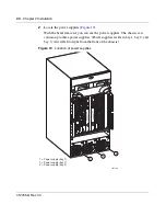
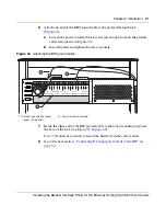
Loosen the 2 retaining screws on the power supply located in bay 1 in the
lower chassis (
Figure 20
).
Figure 20
Loosening the power supply retaining screws
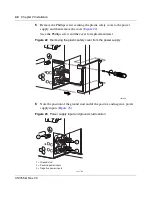
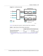
4
Lift the extractor lever to disconnect the power supply from the backplane
connector, and then pull the power supply partially out of the chassis
(
Figure 21
).
Figure 21
Disconnecting the power supply from the chassis backplane
10424FA
+DC
-DC
+DC
-DC
+DC
-DC
10425FA
+DC
-DC
+DC
-DC
+DC
-DC
Summary of Contents for 8010co
Page 6: ...6 312755 G Rev 00...
Page 10: ...10 Contents 312755 G Rev 00...
Page 14: ...14 Tables 312755 G Rev 00...
Page 18: ...18 Preface 312755 G Rev 00...


