232
Chapter 13 VPN
NN47923-500
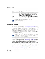
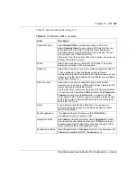
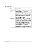
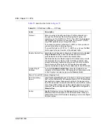
describes the fields in
.
Table 55
VPN Branch Office — IP Policy
Label
Description
Protocol
Enter a number to specify what type of traffic is allowed to go
through the VPN tunnel that is built using this IP policy. For
example, use 1 for ICMP, 6 for TCP, 17 for UDP. 0 is the default
and signifies any protocol. For example, if you select 1 (ICMP),
only ICMP packets can go through the tunnel.
If you specify a protocol other than 1 (ICMP) or 0 (any protocol),
you cannot use the control ping feature.
If you set this field to 6 (TCP) or 17 (UDP), you can use the
Port
field to specify the port number of the allowed traffic.
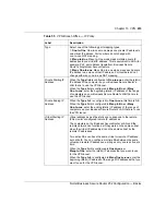
Enable Control Ping
Select the check box and configure an IP address in the
Control
Ping IP Address
field to have the Business Secure Router
periodically test the VPN tunnel to the branch office.
The Business Secure Router pings the IP address every minute.
The Business Secure Router starts the IPSec connection idle
timeout timer when it sends the ping packet. If there is no traffic
from the remote IPSec router by the time the timeout period
expires, the Business Secure Router disconnects the VPN tunnel.
Control Ping IP
Address
If you select
Enable Control Ping
, enter the IP address of a
computer at the branch office. The computer's IP address must be
in this IP policy's remote range (see the
Remote
fields).
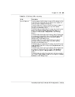
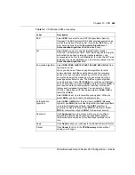
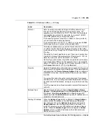
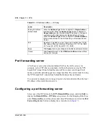
Branch Tunnel NAT Address Mapping Rule
Port Forwarding
Server
Click
Port Forwarding Server
to configure a list of inside (behind
NAT on the LAN) servers, for example, web or FTP. The Business
Secure Router makes these servers visible to the devices using
the VPN branch NAT tunnel (from behind the remote IPSec router)
even though NAT makes your inside network appear as a single
machine. This option applies when the
Type
field is configured to
Many-to-One
.
Active
Enable this feature to have the Business Secure Router use a
different (virtual) IP address for the VPN connection. When you
enable branch tunnel NAT address mapping, you do not configure
the local section.
Summary of Contents for BSR252
Page 28: ...28 Tables NN47923 500 ...
Page 44: ...44 Chapter 1 Getting to know your Business Secure Router NN47923 500 ...
Page 52: ...52 Chapter 2 Introducing the WebGUI NN47923 500 ...
Page 70: ...70 Chapter 3 Wizard setup NN47923 500 ...
Page 96: ...96 Chapter 5 System screens NN47923 500 ...
Page 114: ...114 Chapter 7 WAN screens NN47923 500 Figure 27 WAN IP ...
Page 120: ...120 Chapter 7 WAN screens NN47923 500 Figure 31 Dial Backup Setup ...
Page 128: ...128 Chapter 7 WAN screens NN47923 500 ...
Page 152: ...152 Chapter 9 Static Route screens NN47923 500 ...
Page 194: ...194 Chapter 11 Firewall screens NN47923 500 ...
Page 210: ...210 Chapter 13 VPN NN47923 500 Figure 67 Summary IP Policies ...
Page 222: ...222 Chapter 13 VPN NN47923 500 Figure 71 VPN Branch Office rule setup ...
Page 256: ...256 Chapter 13 VPN NN47923 500 Figure 81 VPN Client Termination advanced ...
Page 260: ...260 Chapter 13 VPN NN47923 500 ...
Page 264: ...264 Chapter 14 Certificates NN47923 500 Figure 83 My Certificates ...
Page 270: ...270 Chapter 14 Certificates NN47923 500 Figure 85 My Certificate create ...
Page 274: ...274 Chapter 14 Certificates NN47923 500 Figure 86 My Certificate details ...
Page 282: ...282 Chapter 14 Certificates NN47923 500 Figure 89 Trusted CA details ...
Page 298: ...298 Chapter 14 Certificates NN47923 500 ...
Page 316: ...316 Chapter 16 IEEE 802 1x NN47923 500 ...
Page 320: ...320 Chapter 17 Authentication server NN47923 500 Figure 106 Local User database edit ...
Page 328: ...328 Chapter 17 Authentication server NN47923 500 ...
Page 376: ...376 Chapter 20 Logs Screens NN47923 500 Figure 150 Log settings ...
Page 386: ...386 Chapter 20 Logs Screens NN47923 500 ...
Page 393: ...Chapter 21 Call scheduling screens 393 Nortel Business Secure Router 252 Configuration Basics ...
Page 394: ...394 Chapter 21 Call scheduling screens NN47923 500 ...
Page 410: ...410 Chapter 22 Maintenance NN47923 500 ...

