18
Carrier Remote IPE product description
Remote Carrier Interface cards (refer to
Figure 9 "Local Carrier Interface
card DIP-switch positions and function" (page 67)
and
Carrier Interface card DIP-switch locations and functions" (page 89)
).
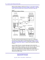
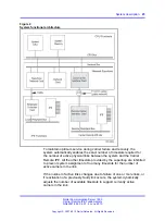
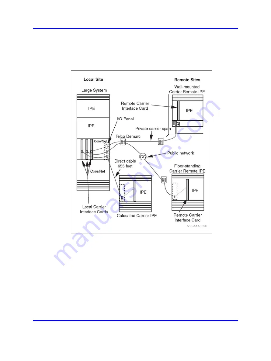
Figure 1
Local system to Remote IPE links
The only equipment specifically designed to support this configuration
are the types of cards, cables, and cabinets listed previously in
"Local site carrier hardware list" (page 13)
and
IPE module hardware list" (page 14)
. All the other equipment is standard
hardware.
At the local site, there are two cables that plug into the Local Carrier
Interface card faceplate connectors. At the other end, the cable connectors
connect to the I/O panel connectors at the rear of the local network
module. At the remote site, two cables that plug into the backplane
connectors behind the Remote Carrier Interface card contain connectors
that are also plugged into the I/O panel connectors at the rear of the
Carrier Remote IPE module.
Nortel Communication Server 1000
Carrier Remote IPE Fundamentals
NN43021-555 04.01
4 June 2010
Copyright © 2007-2010 Nortel Networks. All Rights Reserved.
.
Summary of Contents for Communication Server 100
Page 213: ......


