Functional description
27
or a maximum of 81 timeslots are used for an E1 link with three active
carriers. Timeslots that are not associated with physical T1 or E1 carriers
are disabled. This prevents assigning carrier-inaccessible timeslots to the
intelligent peripheral equipment.
The main Local Carrier Interface card provides the following functions:
•
provides from one to three dedicated T1 or E1 carrier links to connect
the Carrier Remote IPE to the system
•
assigns specific network timeslots to each T1 or E1 carrier link to
communicate with the intelligent peripheral equipment
•
synchronizes the system Clock Controller with the clock signal recover
from the carrier link
•
manages the carrier administration, maintenance, performance
monitoring, and automatic carrier reconfiguration
•
provides a miscellaneous timeslot (timeslot 2) in each T1 or E1 link to
support multiplexed Card-LAN, SDI transport, system monitor, and
carrier maintenance information
•
supports two signaling timeslots (timeslots 0 and 1) in each carrier link
to transmit signaling information across the link
•
provides elastic store (two frames long) to compensate for delays
between different carriers in the link and allow for proper alignment of
all the timeslots on the Internal Voice/Data (IVD) bus
•
provides an interface for system power and alarm monitoring
•
provides an interface for a maintenance port
•
provides continuity test pattern generation and detection for loopback
testing
•
performs diagnostic self-tests during power-up and also when
requested by the CPU
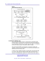
Figure 6 "Local Carrier Interface card functional block diagram" (page
28)
shows the Local Carrier Interface card block diagram illustrating major
functional blocks.
Nortel Communication Server 1000
Carrier Remote IPE Fundamentals
NN43021-555 04.01
4 June 2010
Copyright © 2007-2010 Nortel Networks. All Rights Reserved.
.
Summary of Contents for Communication Server 100
Page 213: ......


