Local equipment installation
75
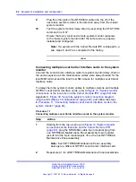
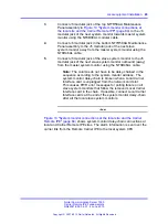
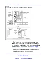
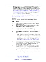
connector of the NT7R66BA MMI Cable into the P3 DB-9
male connector of the NT7R67DA cable.
•
Plug the DB-25 male connector of the NT7R66BA MMI Cable
into a DB-25F/DB-25M nullmodem.
•
Connect the nullmodem DB-25 male connector to the
modem DB-25 female connector. Use the appropriate gender
changer, if required.
3
Make a MMI terminal connection using an A/B switch box:
•
Connect the P3 of the NT7R67DA Local External
Maintenance Cable assembly DB-9 male connector into the
DB-9 female connector of the NT7R66BA MMI Cable.
•
Plug the DB-25 male and of the NT7R66BA MMI Cable into
the A/B switch box DB-25 female C connector.
•
From the switch box, connect a local MMI terminal directly
to the A position on the switch box using a standard
DB-25M/DB-25M straight-through cable.
Alternatively, connect a distant MMI terminal over a standard
DB-25M/DB-25M straight-through cable, a nullmodem, and a
modem to the switch box B position.
4
Terminal/Modem connections over the MSDL Single Terminal
Access:
•
To avoid using the A/B switch box, use three ports on the
MSDL card.
•
Connect one MSDL port to the local MMI terminal.
•
Connect the second MSDL port to a modem.
•
Connect the third MSDL port to the P3 DB-9 male connector
of the NT7R67DA Local External Maintenance Cable
assembly by using the NT7R66BA MMI Cable.
--End--
Connecting a Local Carrier Interface card to the SDI card
Follow the steps in
Procedure 7 “Connecting a Local Carrier Interface card
to connect a Local Carrier Interface card to the
SDI card.
Refer to
Figure 26 "Single LCI connection diagram (local site connections)"
to see the SDI connection diagram.
Nortel Communication Server 1000
Carrier Remote IPE Fundamentals
NN43021-555 04.01
4 June 2010
Copyright © 2007-2010 Nortel Networks. All Rights Reserved.
.
Summary of Contents for Communication Server 100
Page 213: ......


