88
Equipment installation and configuration
•
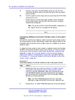
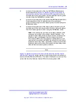
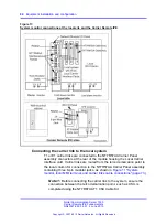
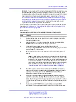
Re-connect the system monitor daisy-chain to include new
Local Carrier Interface cards.
•
Test the system monitor daisy-chain by executing the
STAT
XSM
command in LD 37 to ensure that every local and remote
system monitor or Remote Carrier Interface card system
monitor emulation in the remote cabinet is responding to the
master system monitor.
Table 12 "Remote Carrier Interface standard (default) switch
settings" (page 88)
lists the default (factory-provided switch
settings) for the Remote Carrier Interface card. These settings
are used in the majority of applications; however, if different
settings are required, change the switch settings before installing
the Remote Carrier Interface card.
Table 12
Remote Carrier Interface standard (default) switch settings
Switch positions
Switch
1
2
3
4
5
6
7
8
SW1
OFF
ON
ON
OFF
OFF
OFF
OFF
OFF
SW11
OFF
OFF
OFF
OFF
ON
OFF
OFF
OFF
SW2
OFF
ON
OFF
ON
-
-
-
-
SW3
ON
OFF
ON
ON
-
-
-
-
SW4
ON
ON
OFF
OFF
-
-
-
-
SW5
OFF
ON
OFF
ON
-
-
-
-
SW6
ON
OFF
ON
ON
-
-
-
-
SW7
ON
ON
OFF
OFF
-
-
-
-
SW8
OFF
ON
OFF
ON
-
-
-
-
SW9
ON
OFF
ON
ON
-
-
-
-
SW10
ON
ON
OFF
OFF
-
-
-
-
Figure 14 "Remote Carrier Interface card DIP-switch locations
and functions" (page 89)
shows the NT7R52AA Remote Carrier
Interface card DIP switches. SW2 through SW10 select the
carrier characteristic. SW1 and SW11 define repeater distance,
baud rate, and system monitor address.
Nortel Communication Server 1000
Carrier Remote IPE Fundamentals
NN43021-555 04.01
4 June 2010
Copyright © 2007-2010 Nortel Networks. All Rights Reserved.
.
Summary of Contents for Communication Server 100
Page 213: ......


