background image

Carrier Remote IPE fault isolation and correction

165

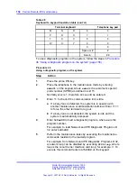
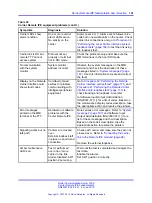
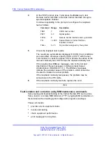
If carrier 2 is configured as a spare, the traffic is handled
by carrier 0 and carrier 1 reducing the traffic capacity to
2/3; by providing a spare, established calls are protected
if one of the primary carrier links fails.

Note: If overload conditions are indicated by OVDxxx
messages, refer to Software Input Output Administration
(NN43001-611) 
() for the message description and indication
of the problem.

4

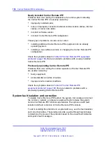
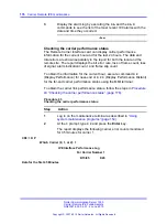
If the message indicates that the Local Carrier Interface card is
faulty, replace the card.

--End--

Performing the Local Carrier Interface card self-test

If the Local Carrier Interface card is faulty, conduct the self-test to verify
that it is actually faulty before replacing it. This test verifies the basic Local
Carrier Interface card functions and outputs a fail or pass message after
the test is completed.

To start the self-test, follow the steps in

Procedure 38 “Performing the

Local Carrier Interface card self-test” (page 165)

.

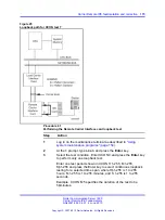
Procedure 38
Performing the Local Carrier Interface card self-test

Step

Action

1

Log in on the maintenance terminal as described in

“Using

system maintenance programs” (page 154)

.

2

At the prompt, type

LD 32

and press the Enter key to access

the Network and IPE Diagnostic Program.

3

Type

DISL sl

and press the Enter key to disable the Local

Carrier Interface card, where

sl

is the Local Carrier Interface

card superloop number to be disabled.

4

Type

XNTT sl

and press the Enter key to start the self-test,

where sl is the Local Carrier Interface card superloop number
specified for the self-test.

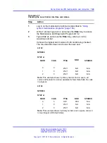
If the response is:

TEST PASSED

Nortel Communication Server 1000

Carrier Remote IPE Fundamentals

NN43021-555 04.01

4 June 2010

Copyright © 2007-2010 Nortel Networks. All Rights Reserved.

.

Summary of Contents for Communication Server 100

Page 1: ...Nortel Communication Server 1000 Carrier Remote IPE Fundamentals Release 7 0 Document Revision 04 01 www nortel com NN43021 555 ...

Page 2: ...ate and reliable except as otherwise expressly agreed to in writing NORTEL PROVIDES THIS DOCUMENT AS IS WITHOUT WARRANTY OR CONDITION OF ANY KIND EITHER EXPRESS OR IMPLIED The information and or products described in this document are subject to change without notice Nortel Nortel Networks the Nortel logo and the Globemark are trademarks of Nortel Networks All other trademarks are the property of ...

Page 3: ...unctional description 25 Local Carrier Interface card 26 Remote Carrier Interface card 30 Engineering guidelines 35 Carrier Remote IPE capacity 35 Traffic engineering 38 System planning and ordering 45 System selection 45 Carrier Remote IPE site planning 46 Equipment installation and configuration 51 Contents 51 Introduction 51 Quick reference to system installation and configuration 51 Installati...

Page 4: ...rrier link to the Remote IPE module 96 Carrier Remote IPE cabinet installation 98 Installing the Carrier Remote IPE cabinet 99 Removing the fiber I O bracket assembly 102 Installing the NT7R94AA Remote Cabinet Cable Assembly 103 Installing cards into the Carrier Remote IPE cabinet 104 Connecting carrier links to the Carrier Remote IPE cabinet 106 Connecting remote MMI terminal and subscriber loop ...

Page 5: ...t isolation and correction 158 Carrier Remote IPE fault isolation and correction 160 Local Carrier Interface card fault isolation and correction 162 Remote Carrier Interface card fault isolation and correction 170 Fault isolation and correction using MMI maintenance commands 174 Replacing Carrier Remote IPE cards 181 Unpacking replacement cards 182 Removing and replacing a card 182 Reinstalling co...

Page 6: ...6 Nortel Communication Server 1000 Carrier Remote IPE Fundamentals NN43021 555 04 01 4 June 2010 Copyright 2007 2010 Nortel Networks All Rights Reserved ...

Page 7: ...ication Server 1000 Release 5 0 are applicable to Communication Server 1000 Release 5 5 May 2007 Standard 01 01 This document is issued to support Communication Server Release 5 0 This document is renamed Carrier Remote IPE Fundamentals and contains information previously contained in the following legacy document now retired Fiber Remote IPE 553 3021 555 No new content has been added for Communic...

Page 8: ...uipment However there are some additional carrier specific commands that can be executed using the Man Machine Interface MMI terminal to specifically control carrier equipment Note on legacy products and releases This document contains information about systems components and features that are compatible with Nortel Communication Server 1000 Release 5 5 software For more information on legacy prod...

Page 9: ...0M Multi Group Meridian 1 PBX 81C CS 1000M Multi Group Intended audience This document is intended for individuals who are responsible for planning engineering installing and maintaining the Carrier Remote IPE as part of a CS 1000M Large Systemor Meridian 1 Large System Conventions Terminology The following systems are referred to generically as Large System Communication Server 1000M Half Group C...

Page 10: ...ng NN43021 220 Communication Server 1000M and Meridian 1 Large System Installation and Commissioning NN43021 310 Communication Server 1000M and Meridian 1 Large System Upgrades Overview NN43021 458 Communication Server 1000M and Meridian 1 Large System Maintenance NN43021 700 Online To access Nortel documentation online click the Technical Documentation link under Support Training on the Nortel ho...

Page 11: ...dian 1 Large Systems are Private Branch Exchange PBX systems that support Carrier Remote IPE service In addition to supporting local subscribers each system can be configured as a distributed system that supports remote subscribers using Carrier Remote IPE modules in a column or Carrier Remote IPE cabinets They are connected to the PBX at long distances using T1 or E1 carrier facilities To support...

Page 12: ...column or Carrier Remote IPE cabinet at a remote site and connect it using T1 or E1 carrier links or direct copper connection if the distance is less or equal to 200 meters or 655 feet to an existing system Table 2 Local site carrier hardware list page 13 and Table 3 Remote Carrier IPE module hardware list page 14 list specific equipment required to support the Carrier Remote IPE at the local site...

Page 13: ...he P1 DB 25 male connector plugs into the faceplate the P2 DB 15HD male connector plugs into the NT7R58AA Maintenance Panel assembly which provides two 6 pin modular system monitor jacks and one DB 9 female MMI maintenance connector The P3 DB 15HD female connector plugs into the NT7R57AA Carrier Panel assembly which provides three 8 pin modular carrier jacks Refer to Appendix C Figure 26 Single LC...

Page 14: ...tor NT8D46AL System Monitor Serial Link Cable Connects the 6 pin modular jack J5 on the NT7R58AA Maintenance Panel assembly to the system monitor jack J6 in the pedestal NT8D93AJ XSDI I O to DTE or DCE Cable This is a DB 9 male to DB 25 male 4 8 m 16 foot cable used to connect the SDI Paddleboard to the NT7R67DA Local External Maintenance Cable P2 DB 9 female connector The entire NT7R66AA SDI Cabl...

Page 15: ... NT7R61AA Maintenance Panel assembly provides one 6 pin modular jack for system monitor and one DB 9 male MMI port connector Refer to Appendix C Figure 28 Remote Carrier IPE module connection diagram single RCI configuration page 200 NT7R67EA Coaxial Interface Adapter Cable Cable with one 8 pin modular plug that plugs into the NT7R68AA Remote Carrier Alarm Panel Assy 8 pin modular jack and two BNC...

Page 16: ...itor and MMI connections Consists of the NT7R68NA cable that connects with P1 DB 9 male connector to the TTY connector on the backplane and is already connected to the NT7R61AA Maintenance Panel assembly with the DB 15 male P2 cable connector The DB 15 female P3 cable connector must be plugged into the NT7R60AA Carrier Alarm Panel assembly connector during cable installation The NT7R61AA Maintenan...

Page 17: ...connected to the NT7R61AA Maintenance Panel assembly with the DB 15 male P2 cable connector The DB 15 female P3 cable connector must be plugged into the NT7R60AA Carrier Alarm Panel assembly connector during cable installation The NT7R61AA Maintenance Panel assembly provides a DB 9 male MMI port connector Refer to Appendix C Figure 29 Remote Carrier IPE cabinet connection diagram single RCI config...

Page 18: ...mote Carrier IPE module hardware list page 14 All the other equipment is standard hardware At the local site there are two cables that plug into the Local Carrier Interface card faceplate connectors At the other end the cable connectors connect to the I O panel connectors at the rear of the local network module At the remote site two cables that plug into the backplane connectors behind the Remote...

Page 19: ...rrier Remote IPE column Floor standing Carrier Remote IPE column includes a pedestal one or more standard NT8D37 IPE Modules and a top cap The IPE module houses a maximum of 16 line cards and a Remote Carrier Interface card Each Remote Carrier Interface card supports IPE cards in only one IPE module Therefore each IPE module requires a Remote Carrier Interface card and one to three T1 or E1 carrie...

Page 20: ...6 through 19 in the expansion cabinet are not configurable and must not be used The main and the expansion cabinets are interconnected by a cable that plugs into the P1 connector located in the lower left hand corner of each cabinet s backplane The T1 or E1 carrier link is connected to the Remote Carrier Interface card through P2 and P3 backplane connectors These backplane connectors are connected...

Page 21: ...er Remote IPE functions are controlled by the system CPU and the firmware in the Local Carrier Interface and Remote Carrier Interface cards The CPU uses software instructions to execute call processing administration and diagnostic functions These functions can be divided into three basic categories CPU functions Network functions IPE functions Nortel Communication Server 1000 Carrier Remote IPE F...

Page 22: ...one carrier has a lower error rate than the other carriers in the link the system selects the carrier with the lowest error rate for signaling and message extraction A T1 or an E1 carrier link between the Local Carrier Interface card and a Remote Carrier Interface card can be configured with one to three carrier links where all three links carry traffic or where one of the two links can be assigne...

Page 23: ...y the superloop are inhibited to prevent system assignment of too many timeslots for the number of active carriers in the link If the number of active links changes due to failure of one or more links or if reactivation of a previously faulty link occurs the system dynamically adjusts the number of available timeslots to support currently active carriers in the link Nortel Communication Server 100...

Page 24: ...r Interface card installed in the Carrier Remote IPE module or cabinet The system provides these network functions performs hardware initialization and self test upon power up establishes call connections between stations connected to Remote IPE line cards and stations local to the system or to trunks for long distance trunk calls over public or private networks communicates switching peripheral s...

Page 25: ... system is controlled by the CPU The CPU performs read write functions on the network control and status registers and communicates with the network equipment over the CPU bus Through these messages the CPU monitors the system status provides call connection sequences monitors traffic activities downloads application software and configuration data and performs system administration and diagnostic...

Page 26: ...network module The Local Carrier Interface card occupies one network card slot and supports a maximum of 120 timeslots for voice and data transmission with the Remote Carrier Interface card A subset of these available timeslots are dynamically activated depending on T1 or E1 carrier and the number of active links in the carrier link A maximum of 63 timeslots are used for a T1 link with three activ...

Page 27: ...imeslot 2 in each T1 or E1 link to support multiplexed Card LAN SDI transport system monitor and carrier maintenance information supports two signaling timeslots timeslots 0 and 1 in each carrier link to transmit signaling information across the link provides elastic store two frames long to compensate for delays between different carriers in the link and allow for proper alignment of all the time...

Page 28: ...tasks they control The MPU is highly integrated and provides most of the decision making logic on the chip Functions of the MPU include controllers timers control and arbitration logic address decoding dual port RAM and independent direct memory access input output ports and independent full duplex serial communication channels that support various protocols The MPU can be reset by powering up the...

Page 29: ... transmit and receive channels on the CPU bus Network bus interface The network bus interface performs two major functions converts bit interleaved serial data received from the network bus into byte interleaved data for transmission over the timeslots used by the IVD bus accepts byte interleaved data transmitted from the IVD bus and converts it into a bit interleaved data stream for transmission ...

Page 30: ... the link If the transmission is degraded or fails the Local Carrier Interface card automatically transfers to the spare link if equipped Remote Carrier Interface card The Remote Carrier Interface card is a microprocessor controlled peripheral interface between the Local Carrier Interface card and the Remote IPE line cards To communicate with the Local Carrier Interface card the Remote Carrier Int...

Page 31: ...n different carriers in the link This allows for proper timeslot alignment of all carriers on the IVD bus Provides a distance selectable DIP switch that selects the distance from the Remote Carrier Interface card to the first signal regenerator such as a repeater a CSU or an LTU in the carrier link to be from 0 to 200 m 0 to 655 ft Converts SSD type signaling format received from the Local Carrier...

Page 32: ...hannels over the carrier timeslot 2 Tasks that the MPU performs depend on the interrupts it receives These interrupts are prioritized by the importance of the tasks they control The MPU is highly integrated and provides most of the decision making logic on the chip Functions of the MPU include controllers timers control logic address decoding dual port RAM and independent direct memory access para...

Page 33: ...ugh the Remote Carrier Interface card to transmit maintenance messages which include LED control of the IPE card enable disable Peripheral card configuration Peripheral card type and version information IPE interface The IPE interface links IPE cards to the Remote Carrier Interface MPU using sixteen DS 30X loops one for each IPE card and contains the following Remote Carrier Interface circuits Dua...

Page 34: ...1 or E1 carrier interface performs the following functions Connects the system to Remote IPE using one to three T1 or E1 carrier links Provides a distance selectable switch that selects the distance from the Remote Carrier Interface card to the first signal regenerator such as a repeater a CSU or an LTU in the carrier link to be from 0 to 200 m 0 to 655 ft Transmits signaling information across th...

Page 35: ...se ports are located at one or more remote sites The overall system capacity does not change by installing Carrier Remote IPE The difference between a system with Carrier Remote IPE and without Carrier Remote IPE is the distribution of line cards that is the subscriber loops Carrier Remote IPE allows distribute the intelligent peripheral equipment to be distributed at long distances from the syste...

Page 36: ...60 main cabinet and an NTBK70 expansion cabinet The main cabinet supports the Remote Carrier Interface card and up to ten IPE cards or 160 ports If more ports are required an expansion cabinet can be installed adjacent to the main cabinet These two cabinets are linked with an inter cabinet cable that plugs into 50 pin connector P1 located at the bottom left hand corner of each cabinet This cable e...

Page 37: ...ired before the carrier link exits the building The carrier link line coding is B8ZS The source of the clock for the carrier links is the local system The preferred framing for the T1 link is ESF D4 is also supported Engineering the E1 carrier link An E1 carrier link can be constructed using coaxial cable or twisted pair wire over the private or public network When engineering a carrier link deter...

Page 38: ...interface to the carrier link are designed for in house environment carrier protection To protect the carrier link in the external environment which is susceptible to lightning external line protection circuits similar to trunk protection circuits are required before the carrier link exits the building The T1 carrier link line coding is B8ZS The E1 carrier link line coding is HDB3 The source of th...

Page 39: ...ilable channels for any specific configuration in the CO or CO network are at least equal to the channels on the carrier to provide the GOS required One Local Carrier Interface card is connected to one Remote Carrier Interface card only There is no concentration option on the Carrier Remote IPE One carrier out of two or one carrier out of three equipped is allowed to be a spare which serves as a b...

Page 40: ... a cabinet is equipped with no more than 10 cards All line trunk cards card slot and carrier calculations are to be rounded up to the next higher integer number Capacity calculations of lines and trunks allowed per carrier should be rounded down to the next lower number When several IPE modules or Carrier Remote IPE cabinets are required in the configuration it is preferable to fill up the first I...

Page 41: ...umber of lines divided by 16 the number of trunks divided by 8 or the number of integrated voice and data lines divided by 32 to obtain the number of card slots required An IPE module has 16 card slots A Carrier Remote IPE cabinet has 10 card slots If the number of card slots is less than or equal to 16 or 10 the resulting configuration is within the traffic capacity of the carrier provided If the...

Page 42: ...cabinets will be needed Use only columns with 1 or 2 carriers in Table 5 Carrier capacity calculations page 39 if a spare carrier is to be used The port counts in the final configuration should be within the slot limitation of the Carrier Remote IPE enclosure 16 for IPE module 10 for the Main Carrier Remote IPE cabinet and 6 for the Expansion Carrier Remote IPE cabinet End Engineering examples Eng...

Page 43: ...but within the capacity of four carriers two lines of two carrier links Note that the integrated lines alone generate more traffic 1600 CCS than two carriers can handle they need to be split between two IPE modules or Carrier Remote IPE cabinets 3 Calculate card slots 80 80 32 20 8 5 3 8 There are sufficient card slots in one cabinet to handle the required ports Even though the configuration excee...

Page 44: ... application is also acceptable However future growth should be kept to 42 lines maximum at each cabinet Blocking Network one IPE module and one Carrier Remote IPE cabinet Example 4 A university providing E1 carrier telephone services to 400 boarding students is located one mile away from the main administrative building where the local system is located Find the configuration required to serve th...

Page 45: ...er to Communication Server 1000M and Meridian 1 Large System Planning and Engineering NN43021 220 for overall system information To obtain specific planning and ordering information for T1 and E1 carrier links interfacing with network and peripheral cards see the following sections System selection Determine the type of Carrier Remote IPE enclosure This selection may be dictated by the installatio...

Page 46: ...Remote IPE cabinet system type if the system size requirement is less than ten IPE cards To expand this type of system beyond ten IPE cards add a Carrier Remote IPE expansion cabinet adjacent to the main and install up to six IPE cards into the first six IPE card slots of the expansion cabinet Carrier Remote IPE site planning When selecting a site for the Carrier Remote IPE consider the number of ...

Page 47: ... card and up to ten IPE cards The expansion cabinet requires its own separate power supply to provide power to an additional six IPE cards The Carrier Remote IPE cabinet can be powered with an AC power system using the NTAK04 AC DC power supply It can also be powered with a DC power system using the NTAK05 DC power supply from a 52 V battery source through the NTAK28AA Junction box and the NTAK041...

Page 48: ...lar jacks E1 carrier links may in some cases use coaxial cables 75 ohm impedance and terminate into BNC connectors requiring an RJ 48 to BNC adapters supplied with the equipment to connect the link to the Carrier Panel assembly at the UEM I O panel Carrier equipment planning form Table 8 Planning form page 48 displays a planning form to use when ordering carrier equipment Enter the part number and...

Page 49: ...ble 2 Local site carrier hardware list page 13 Table 4 Carrier Remote IPE wall mounted cabinet hardware list page 16 starting on Table 2 Local site carrier hardware list page 13 Item Part Number Quantity at local site Quantity at Remote IPE Nortel Communication Server 1000 Carrier Remote IPE Fundamentals NN43021 555 04 01 4 June 2010 Copyright 2007 2010 Nortel Networks All Rights Reserved ...

Page 50: ...50 Carrier Remote IPE product description Nortel Communication Server 1000 Carrier Remote IPE Fundamentals NN43021 555 04 01 4 June 2010 Copyright 2007 2010 Nortel Networks All Rights Reserved ...

Page 51: ...nstallation and configuration If familiar with the system operation and general installation practices follow the steps below and refer to Connection diagrams and external connectors pin assignment page 197 for connection diagrams to speed up the installation of the Remote Carrier IPE at the local and remote sites 1 Take inventory of the carrier equipment by comparing the received equipment agains...

Page 52: ...69 Connection diagrams and external connectors pin assignment page 197 Figure 26 Single LCI connection diagram local site connections page 198 Figure 27 Multiple LCIs connection diagram local site daisy chain connection page 199 Figure 10 Local Carrier Interface card faceplate cable connections in Meridian 1 PBX 61C page 70 6 Install the system monitor local MMI terminal and carrier link cables to...

Page 53: ...all the NT7R52 Remote Carrier Interface card into the Cont card slot in the IPE Module or the Carrier Remote IPE cabinet Also install the power supply and the IPE cards 10 Install the internal cable assemblies For the Carrier Remote IPE column refer to Installing the backplane cable assemblies page 91 Figure 28 Remote Carrier IPE module connection diagram single RCI configuration page 200 Figure 1...

Page 54: ...rs page 122 13 Conduct system acceptance testing Refer to Carrier Remote IPE acceptance testing page 133 Installation overview Carrier Remote IPE service can be added to an existing system originally installed and operating without Carrier Remote IPE or it can be an integral part of a newly installed system In either case the connection of the Carrier Remote IPE to the system over T1 or E1 carrier...

Page 55: ...he pre installation procedures to prepare the site before installing and connecting the equipment The general preinstallation and installation points are listed below The actual installation procedure steps start in Local equipment installation page 63 Preinstallation procedures include ordering carrier service from telco preparing the site unpacking and inspecting the equipment taking an inventor...

Page 56: ...llation preparation consists of the following preparing the site unpacking and inspection taking inventory selecting the network slot for the Local Carrier Interface card installing the card selecting the T1 or E1 carrier link preparing the remote site cables grounding power source and the space for the Remote IPE column or cabinets Preparing the site When preparing a site consider environmental s...

Page 57: ...ment for obvious faults or damage Report any damaged component to the sales representative and the carrier who delivered the equipment Hold the plug in cards by their nonconductor edges and keep them in their antistatic bags until ready to install them Do not stack the plug in cards on top of each other Taking inventory After the equipment has been unpacked and visually inspected verify that all t...

Page 58: ...point CSU and the Local Carrier Interface card at the local site and the Remote Carrier Interface card at the remote site as a preinstallation procedure Route twisted pairs for T1 or E1 carrier links from the telco demarcation point to the carrier equipment Use standard cable routing procedures to prevent cable exposure to possible damage from contact with machine and human traffic Terminate the t...

Page 59: ... SG Meridian 1 PBX 61C Card slots 0 7 NT5D21 Core Net work Module CS 1000M SG Meridian 1 Option 61C Meridian 1 Option 51C 0 7 NT8D35 Network Module CS 1000M MG Meridian 1 PBX 81C Meridian 1 Option 81C Meridian 1 Option 81 5 10 11 12 See Note NT9D11 Core Net work Module CS 1000M SG Meridian 1 Option 61C 0 1 See Note 2 7 NT6D39 CPU Net work Module Meridian 1 Option 61C 1 2 See Note 3 8 Note Card slo...

Page 60: ...use the Carrier Remote IPE Connection Record label below to record the installation characteristics for each Local Carrier Interface card Network Module I O Panel connector cutouts selection When installing the carrier remote panel assemblies for each Local Carrier Interface card use the following recommendations Use Local Carrier Interface card I O extension cables NT7R69AA and NT7R69BA if it is ...

Page 61: ...erface card carrier panel assemblies installation to avoid cable congestion on the right hand side if possible Use side by side connector cutouts for the Local Carrier Interface card panel assemblies starting at the top of the I O panel This avoids obstruction of internal cable way and associates the carrier panel assemblies with their respective Local Carrier Interface cards Note The current left...

Page 62: ...used to install its Carrier and Maintenance Panel Assemblies for that specific Local Carrier Interface card If the label is not available make a label and paste it on the module Figure 8 Carrier Remote IPE Connection Record label Label entries description Remote Site Name of the Remote Carrier IPE site associated with this Local Carrier Interface card superloop number SUPC Local Carrier Interface ...

Page 63: ...n of the master system monitor or to the next LCI SUPCxxx J6 in the direction of the master system monitor J6 can be connected to J5 of the next system monitor in the direction away from the master system monitor or to J5 of the next LCI SUPCxxx in the direction away from the master system monitor where xxx in SUPCxxx is the superloop number of the Local Carrier Interface card in the daisy chain T...

Page 64: ...r if the Local Carrier Interface card is not installed follow the steps in the next section Installing the Local Carrier Interface card Procedure 3 Installing the Local Carrier Interface card page 64 describes how and where to install the Local Carrier Interface cards In a new system the card is shipped installed in a network card slot from the factory However it can be necessary to install additi...

Page 65: ...ly push the locking device levers toward the faceplate to insert the card connector into the backplane connector and lock the card in place 6 Set the ENB DIS switch on the NT7R51 Local Carrier Interface card to ENB and observe the card LED at the top of the faceplate as the Local Carrier Interface card performs self tests The card LED should blink three times and then stay lit until enabled by sof...

Page 66: ... ON OFF ON SW6 ON OFF ON ON SW7 ON ON OFF OFF SW8 OFF ON OFF ON SW9 ON OFF ON ON SW10 ON ON OFF OFF Figure 9 Local Carrier Interface card DIP switch positions and function page 67 shows the Local Carrier Interface card DIP switches SW1 through SW11 and their functions Nortel Communication Server 1000 Carrier Remote IPE Fundamentals NN43021 555 04 01 4 June 2010 Copyright 2007 2010 Nortel Networks ...

Page 67: ...card which are selected on the card with switch SW11 switch positions 1 through 5 refer to Figure 9 Local Carrier Interface card DIP switch positions and function page 67 for the SW11 switch position The address is used to address a specific Local Carrier Interface card in a daisy chain configuration lient Nortel Communication Server 1000 Carrier Remote IPE Fundamentals NN43021 555 04 01 4 June 20...

Page 68: ...1 1 0 0 1 1 0 0 1 1 0 0 1 1 0 0 1 1 0 1 0 1 0 1 0 1 0 1 0 1 0 1 0 1 0 1 0 1 0 1 0 1 0 1 0 1 0 1 0 1 For SUPC 0 124 the Local Carrier Interface card MMI address SW 11 POS 1 5 should match the superloop number For SUPC 128 156 where the Local Carrier Interface card is installed in Network Group 4 the Local Carrier Interface card address cannot match the superloop number but the address must be uniqu...

Page 69: ...t and the MMI terminal connections If an E1 carrier link is a coaxial cable terminated with BNC connectors the NT7R67EA Coaxial Interface Adapter cable 8 pin modular plug to BNC is used to connect the 8 pin modular jacks at the NT7R57AA Carrier Panel assembly to the BNC carrier link connectors Refer to Figure 9 Local Carrier Interface card DIP switch positions and function page 67 and Figure 14 Re...

Page 70: ...rk Module I O Panel connector cutouts selection page 60 recommendations Note The NT7R57AA Carrier and the NT7R58AA Maintenance Panel assemblies together with the NT7R67HA cable are integral parts of the NT7R67BA Local Carrier Monitor Cable Assembly To assist you in connecting the cable assemblies refer to Appendix C Figure 26 Single LCI connection diagram local site connections page 198 To install...

Page 71: ... cutouts 4 Install the NT7R57AA Carrier Panel assembly already connected to the P3 DB 15 HD female connector of the NT7R67BA cable assembly Mount it into the selected I O panel connector cutout so that the 8 pin modular jack tabs are to the left Refer to Figure 11 System monitor local MMI terminal and carrier links cable connections page 73 for connector orientation Fasten the panel to the cutout ...

Page 72: ...ale connector located on the faceplate of the Local Carrier Interface card 3 Plug the DB 9 male P2 connector at the other end of the NT7R67CA cable assembly into the DB 9 female connector on the NT7R58AA Maintenance Panel End Installing SDI and local MMI terminal cables The NT7R67DA External Maintenance Cable Assembly connects the SDI card and the TTY terminal to the DB 9 connector on the NT7R58AA...

Page 73: ...y chain in descending order from the MMI terminal to the SDI port Figure 11 System monitor local MMI terminal and carrier links cable connections page 73 shows the NT7R57AA Carrier Panel and NT7R58AA Maintenance Panel assemblies with the system monitor the SDI TTY and the carrier connections The NT7R58AA Maintenance panel assembly connector is used to connect the SDI port and the local MMI termina...

Page 74: ...male P1 connector at the common end of the NT7R67DA Local External Maintenance Cable assembly into the DB 9 female connector on the NT7R58AA Maintenance Panel assembly Plug the DB 9 male P3 connector of the NT7R67DA cable assembly into the DB 9 female connector of the NT7R66BA MMI Cable Plug the DB 25 male end of the NT7R66BA MMI Cable into the MMI terminal RS 232 connector If it is necessary to c...

Page 75: ...atively connect a distant MMI terminal over a standard DB 25M DB 25M straight through cable a nullmodem and a modem to the switch box B position 4 Terminal Modem connections over the MSDL Single Terminal Access To avoid using the A B switch box use three ports on the MSDL card Connect one MSDL port to the local MMI terminal Connect the second MSDL port to a modem Connect the third MSDL port to the...

Page 76: ... SDI port on an SDI card Plug the DB 25 male connector of the NT7R66AA SDI Cable Kit to connect the DB 25 female SDI connector at the I O panel The DB 25F DB 25F adapter is not used Plug the DB 9 male connector on the NT7R66AA SDI Cable Kit into the P2 connector on the NT7R67DA cable 3 To test the MMI and Host SDI login refer to MMI mode page 120 and Host SDI mode page 121 for login instructions N...

Page 77: ...Carrier Interface cards page 80 and Figure 27 Multiple LCIs connection diagram local site daisy chain connection page 199 Plug the DB 9 male P1 connector at the common end of the NT7R67DA cable into the DB 9 female connector on the NT7R58AA Maintenance Panel assembly that corresponds to Local Carrier Interface card 1 Install the NT7R67DA cable assembly 2 as in step 1 for the Local Carrier Interfac...

Page 78: ... C connector From the switch box a local MMI terminal can be connected directly to the A position on the switch box using a standard DB 25M DB 25M straight through cable As well a distant MMI terminal can be connected over a standard DB 25M DB 25M straight through cable a nullmodem and a modem to the switch box B position 4 Terminal Modem connections over the MSDL Single Terminal Access To avoid u...

Page 79: ...A SDI Cable Kit into the DB 9 female connector into the NT7R67DA cable P2 connector 2 To connect other SDI cards Route and install the DB 9 female P2 connector of the NT7R67DA cable assembly of the Local Carrier Interface card 1 to an available SDI port on an SDI card Plug the DB 25 male connector of the NT7R66AA SDI Cable Kit to connect the DB 25 female SDI connector at the I O panel The DB 25F D...

Page 80: ...nterface cards Connecting the system monitor cables The NT7R58AA Maintenance Panel assembly provides two 6 pin modular jacks to connect to the system monitor located in the pedestal and one DB 9 SDI TTY connector The 6 pin modular jack J5 is used to connect to the system monitor J6 jack in the pedestal as shown in Figure 11 System Nortel Communication Server 1000 Carrier Remote IPE Fundamentals NN...

Page 81: ...re 10 Connecting a single Local Carrier Interface card to the system monitor page 81 Procedure 10 Connecting a single Local Carrier Interface card to the system monitor Step Action 1 Verify existing system monitor daisy chain first by executing the STAT XSM command in LD 37 2 Determine the system monitor addresses for new Carrier Remote IPE column or wall mount cabinet 3 Set master system monitor ...

Page 82: ...ultiple NT7R51 Local Carrier Interface cards refer to Figure 13 System monitor connections at the local site and the Carrier Remote IPE page 84 and Appendix C Figure 30 Local site system monitor connection diagram single and multiple LCI configuration page 202 and follow the steps in Procedure 11 Connecting multiple Local Carrier Interface cards to the system monitor page 82 Procedure 11 Connectin...

Page 83: ...ave to be daisy chained in the sequence according to the system monitor address The system monitor daisy chain is broken when a Local Carrier Interface card is unplugged from the network card slot This causes PWR error messages for polling failure on all slave system monitors that follow the removed Local Carrier Interface card in the chain If possible connect Local Carrier Interface cards at the ...

Page 84: ...e telco demarcation point to the local column for connection to the NT7R57AA Carrier Panel assembly containing three 8 pin modular jacks as shown in Figure 11 System monitor local MMI terminal and carrier links cable connections page 73 Note 1 Before connecting the carrier link to the system ensure the connection between the telco demarcation point such as CSU is completed using the NT7R87AA T1 CS...

Page 85: ...Panel assembly 8 pin modular jack for each T1 carrier link 4 Record the telco carrier circuit ID for each carrier link link 0 1 and 2 Note These carrier circuit IDs will be used at the remote site to identify the links that correspond to carrier 0 1 and 2 at the local site This prevents mismatch of carrier links between the Local Carrier Interface card and the Remote Carrier Interface card Enter t...

Page 86: ...umn floor standing column at the remote site To do this follow the instructions in Communication Server 1000M and Meridian 1 Large System Installation and Commissioning NN43021 310 It describes how to install the pedestal the IPE module and the top cap and how to connect the power the internal and external communication cables and subscriber loops To install the Power Fail Transfer Unit PFTU to th...

Page 87: ... DIP switch locations and functions page 89 Correspondingly Figure 9 Local Carrier Interface card DIP switch positions and function page 67 shows the Local Carrier Interface card DIP switches SW1 through SW11 and their functions Refer to Figure 9 Local Carrier Interface card DIP switch positions and function page 67 for DIP switch settings for the Local Carrier Interface card 3 Determine the syste...

Page 88: ...quired change the switch settings before installing the Remote Carrier Interface card Table 12 Remote Carrier Interface standard default switch settings Switch positions Switch 1 2 3 4 5 6 7 8 SW1 OFF ON ON OFF OFF OFF OFF OFF SW11 OFF OFF OFF OFF ON OFF OFF OFF SW2 OFF ON OFF ON SW3 ON OFF ON ON SW4 ON ON OFF OFF SW5 OFF ON OFF ON SW6 ON OFF ON ON SW7 ON ON OFF OFF SW8 OFF ON OFF ON SW9 ON OFF ON...

Page 89: ...emote Carrier Interface card which are selected using switch SW11 switch positions 1 through 5 A unique address is selected for each Remote Carrier Interface card Refer to Figure 14 Remote Carrier Interface card DIP switch locations and functions page 89 for the SW11 switch location on the card Nortel Communication Server 1000 Carrier Remote IPE Fundamentals NN43021 555 04 01 4 June 2010 Copyright...

Page 90: ... 1 1 1 0 1 1 0 0 1 1 0 0 1 1 0 0 1 1 0 0 1 1 0 0 1 1 0 0 1 1 0 0 1 1 1 0 1 0 1 0 1 0 1 0 1 0 1 0 1 0 1 0 1 0 1 0 1 0 1 0 1 0 1 0 1 4 Pull the NT7R52AA Remote Carrier Interface card locking devices away from the faceplate Holding the card by these locking devices insert it into the card guides in the card slot marked Cont which is located to the right of slot 7 Make sure to use the card guides imme...

Page 91: ...er links system monitor external alarms MMI maintenance port The NT7R68AA Remote Carrier Alarm Cable assembly is routed from the Remote Carrier Interface card to the I O panel connectors that support carrier link and auxiliary or external alarm connections The NT7R68BA Remote Maintenance Cable assembly connects the upper backplane connector SL0 to the I O panel connectors that support the system m...

Page 92: ...en the retaining screw 4 Install the NT7R60AA Carrier Alarm Panel assembly into the recommended J5 empty connector cutout in the I O panel Tighten the retaining screw This panel contains an 8 pin modular jack for carrier 2 at the bottom and a DB 15 HD female auxiliary alarm external alarm connector at the top of the panel assembly 5 Plug the P1 24 pin block connector of the NT7R68AA Remote Carrier...

Page 93: ... or connector cutouts selection recommendation 2 Install the NT7R61AA Maintenance Panel assembly into the recommended J2 connector cutout on the I O panel Tighten the retaining screw 3 Plug the P1 24 pin connector of the NT7R68BA Remote Maintenance Cable assembly into the SL0 connector on the IPE Module s backplane End shows the rear of the Carrier Remote IPE module and cables connecting the backp...

Page 94: ...g column the pedestal contains a slave system monitor used to monitor Carrier Remote IPE system alarms These alarms are reported over the carrier link and the Local Carrier Interface card to the local master system monitor and from there to the CPU The CPU sends PWR alarm messages to the system maintenance TTY identifying the problem Nortel Communication Server 1000 Carrier Remote IPE Fundamentals...

Page 95: ...e NN43001 311 Note Set the system monitor address on the system monitor card in the pedestal to be identical to the system monitor address set on the Remote Carrier Interface card using SW11 switch positions 1 through 5 Set the slave system monitor to the same address that corresponds to the master system monitor at the local site 4 For multiple Carrier Remote IPE modules on a single pedestal conn...

Page 96: ...MI D 9 male connector on the NT7R61AA Remote Maintenance Panel Assembly 4 For multiple Carrier Remote IPE modules at a single site use an A B C switch box to connect each MMI DB 9 male connector on the Maintenance Panel assembly to a single MMI terminal To do this use the NT7R66BA MMI Cable between the A B switch box connector C and the MMI connector on each IPE module Use a DB 25M DB 25M straight...

Page 97: ...el assemblies at the remote site follow the steps in Procedure 18 Connecting the carrier link to the Remote IPE module page 97 Procedure 18 Connecting the carrier link to the Remote IPE module Step Action 1 Route all three carrier links to the rear of the Carrier Remote IPE column housing the Remote Carrier Interface card 2 Identify carrier 0 primary carrier 1 primary and carrier 2 primary or spar...

Page 98: ...commands on the MMI terminal Refer to Verifying carrier link connections at the remote site page 128 7 Secure the carrier link cables with tie wraps as appropriate End The NT7R60AA Maintenance Panel assembly that contains one 8 pin modular jack for carrier 2 also contains the DB 15HD female external alarm input connector This DB 15HD connector connects the NT7R86AA Auxiliary Alarm Cable assembly t...

Page 99: ...0410 power cable Before installing the power supply into the cabinet set switches SW1 through SW 4 as shown in Table 14 NTAK04 AC DC and NTAK05 DC power supply switch settings page 99 Table 14 NTAK04 AC DC and NTAK05 DC power supply switch settings Voltage SW1 SW2 SW3 SW4 Message Waiting 150 V ON Message Waiting 120 V OFF Ringing 86 Vrms OFF OFF OFF Ringing 80 Vrms ON OFF OFF Ringing 75 Vrms OFF O...

Page 100: ...e locations 6 Install the 6 AWG copper ground wire between the approved building ground and the ground lug at the bottom of the cabinet 7 Repeat steps 3 through 6 for the expansion cabinet if required 8 Install the power supply in the Pwr Sup slot in the NT1P70 NT1P60 main cabinet shelf and turn the power switch to OFF 9 At the building ground end of the wire use two fastening clamps to connect th...

Page 101: ...wer cord It should measure 0 ohms If the resistance is greater than 0 ohms check the ground terminal on the power supply power connector for continuity to the chassis Figure 16 Carrier Remote IPE cabinet page 101 shows the Carrier Remote IPE cabinet with the mounting bracket and the mounting holes It also shows the ground lugs for ground connections Figure 16 Carrier Remote IPE cabinet Nortel Comm...

Page 102: ...he card slots from 10 to 15 End This completes the cabinet installation and system ground test Removing the fiber I O bracket assembly The NT1P70 NT1P60 main Carrier Remote IPE cabinet is equipped with a I O bracket assembly used in Fiber Remote IPE This bracket must be removed and the NT7R94AA Remote Cabinet Cable Assembly must be installed in its place Refer to Figure 17 Carrier cable routing fo...

Page 103: ...inge tabs 3 Slide the entire assembly backwards and insert the hinge tabs into the two holes on the bracket 4 Move the front of the assembly by 45 degrees to the right to be at the right angle to the backplane and install the retaining screw 5 Plug the DB 15 male P1 connector at the common end of the NT7R68CA cable assembly into the P3 auxiliary DB 15 female connector located on the backplane 6 Pl...

Page 104: ...Even though the cards are shipped in the cabinet from the factory for safety and ease of installation these cards should have been removed from the cabinet before it was installed it onto the wall To install these cards follow the steps in Procedure 22 Installing cards into the Carrier Remote IPE cabinet page 105 Nortel Communication Server 1000 Carrier Remote IPE Fundamentals NN43021 555 04 01 4 ...

Page 105: ...ition 2 is set to ON to indicate remote site Switches 1 and 11 are read by firmware 2 Pull the Remote Carrier Interface card locking devices away from the faceplate and holding the card by these devices insert the card into the card guides in slot Cont Refer to Figure 16 Carrier Remote IPE cabinet page 101 for card slot positions in the shelf 3 Slide the card into the cabinet until it engages the ...

Page 106: ...Coaxial Interface Adapter Cable to connect the 8 pin modular jacks at the I O panel to the BNC connector on each E1 carrier link coming from the telco demarcation point Also refer to Figure 9 Local Carrier Interface card DIP switch positions and function page 67 and Figure 14 Remote Carrier Interface card DIP switch locations and functions page 89 to set SW1 SW2 SW5 and SW8 for E1 operation and ca...

Page 107: ...minated with BNC connectors use one NT7R67EA Coaxial Interface Adapter cable to connect each 8 pin modular jack on the NT7R59AA Carrier Panel and NT7R60AA Carrier Alarm Panel assemblies to BNC carrier link connectors 5 Identify BNC connectors on each NT7R67EA Coaxial Interface Adapter cable that corresponds to the appropriate carrier carrier 0 carrier 1 and carrier 2 at the NT7R57AA Carrier Panel ...

Page 108: ...hich receives power fail signals from the power supply through the backplane and sends the information over carrier links to the Local Carrier Interface card for processing by the local system CPU Refer to Appendix C Figure 29 Remote Carrier IPE cabinet connection diagram single RCI configuration page 201 for the connection diagram Nortel Communication Server 1000 Carrier Remote IPE Fundamentals N...

Page 109: ...is connected to the MMI connector on the Maintenance Panel Assembly over a modem use the NT7R66BA MMI Cable and a DB 25F DB 25M nullmodem to connect the modem to the MMI D 9 male connector on the NT7R61AA Maintenance Panel Assembly 4 For multiple Carrier Remote IPE modules at a single site use an A B C switch box to connect each MMI DB 9 male connector on the Maintenance Panel assembly to a single...

Page 110: ...em into their respective connectors at the bottom of the cabinet also designated J11 through J16 for card slots 10 through 15 5 Replace the locking bar s in the cabinet s over the cable connectors End Auxiliary alarm connections To connect the auxiliary or external alarm indicators to the NT7R60AA Carrier Alarm Panel assembly connector use the NT7R86AA Auxiliary Alarm Cable assembly Follow the ste...

Page 111: ...e present across the contacts The customer auxiliary alarm feature can be used for any premise alarm application where an alarm condition activates a relay contact closure Figure 19 Subscriber loop tip and ring connectors page 112 shows the subscriber loop tip and ring connectors that link line cards to the MDF and the terminal connection It also shows the MMI terminal connection to the NT7R61AA M...

Page 112: ...ckplane contains P4 a 2 pin power connector which provides a 15 V and 15 V power source for the attendant console To make this connection follow the steps in Procedure 27 Connecting the attendant to the Carrier Remote IPE cabinet page 113 Nortel Communication Server 1000 Carrier Remote IPE Fundamentals NN43021 555 04 01 4 June 2010 Copyright 2007 2010 Nortel Networks All Rights Reserved ...

Page 113: ...the Carrier Remote IPE cabinet Step Action 1 Install the PFTU near the MDF and connect it to the MDF according to the instructions in the PFTU user manual 2 Install the NT7R86AA cable between the PFTU and the NT7R60AA Carrier Alarm Panel assembly connector DB 15 female Alarm connector on the Carrier Remote IPE cabinet For more information on how to install the PFTU refer to Communication Server 10...

Page 114: ...e standard system configuration and administration and do not require special considerations However there are some initial setup functions that must be considered at the local and the remote sites These functions are administered over a Man Machine Interface MMI port connected to a terminal or a TTY at the local and the remote site Nortel Communication Server 1000 Carrier Remote IPE Fundamentals ...

Page 115: ...nal numbers TNs associated with the peripheral controller disable the superloop and remove the data block associated with the peripheral controller Data blocks of one superloop can be moved to a different superloop number using Move Data Blocks Program LD 25 Configure a superloop data block to correspond to the Local Carrier Interface card Configure a peripheral controller data block to correspond...

Page 116: ...are Download PSDL ensures that the latest loadware is downloaded into the Local and Remote Carrier Interface cards PSDL is initiated upon Initialization INIT ENXP after power reset or the Local or Remote Interface card ENXP of the Remote Carrier Interface card by adding peripheral software version parameter after the Peripheral Controller ID ENLL of the Local Carrier Interface card by adding the P...

Page 117: ...ocal Carrier Interface card Table 19 To define a carrier superloop Prompt Response Description REQ CHG Adding a new Local Carrier Interface card TYPE SUPL Adding a superloop for the Local Carrier Interface card SUPL 0 252 Superloop number SLOT L R Superloop card side for the Local Carrier Interface card where L left is default position SUPT CARR Carrier superloop type Prompted when REM_IPE 286 sof...

Page 118: ...To enable the carrier superloop x Command Response Description ENLL x ok prompt Enables specified superloop x To remove the configuration of the Remote IPE superloop load Maintenance and Diagnostic Program LD 32 and execute the DISL x command to disable the superloop and then load Configuration Record Program LD 97 to delete the configuration records of the superloop for the Local Carrier Interfac...

Page 119: ...ormance status page 176 LD 32 NPR000 STAT sl CARR CALS TTSA NND SPARED 0 0 21 21 NO NOT SPARED 1 0 21 21 NO NOT SPARED 2 0 N A N A AVAIL Parameter description CARR Carriers 0 1 and 2 carrier 0 has priority over carrier 1 when sparing carrier links CALS Carrier Alarm Status 0 indicates Alarm Level 0 indicates no alarm TTSA Timeslots currently available for voice and data n 21 for T1 and n 27 for E1...

Page 120: ...o and some display functions at the distant site The default MMI interface characteristics are set in the Local and Remote Carrier Interface card EEPROM as follows Speed 2400 bps speed is an exception it is selected using DIP SW1 position 1 where OFF 2400 bps and ON 1200 bps Character width 7 Parity bit mark Stop bit 1 The MMI mode is accessed from the initial INIT mode by entering L on the MMI te...

Page 121: ... terminal to go from one mode to the next Figure 21 TTY or terminal modes at the local and the remote sites Host SDI mode In the Host SDI mode a terminal is connected to the MMI port at the Carrier Remote IPE This terminal becomes the local maintenance and service change TTY At the local site the Local Carrier Interface card connects to the MMI port and to an SDI port of an SDI card Nortel Communi...

Page 122: ...CRI Prompt after logging in Enter Password M1LINK Type in the password CRI HO To access the Host SDI mode Enter Password HOST Enter the password HOST The Host SDI mode is accessed from the MMI mode by entering HOST at the terminal or TTY In this mode the entire local system can be configured and maintained shows that for example LD 45 can be activated to perform loopback testing To exit this mode ...

Page 123: ...IPE S N L1105 A4 Software Version 1 00 8 17 95 10 48 Local Site Alarm Enabled YES Self Clearing Enabled YES Sparing Enabled Disabled Enabled All Link Maps Normal Alarm Level 1 Threshold Value E 6 Threshold Duration in seconds 1 Alarm Level 2 Threshold Value E 5 Threshold Duration in seconds 1 Alarm Level 3 Threshold Value E 4 Threshold Duration in seconds 1 Frame Slip Alarm Level Threshold 100 Thr...

Page 124: ... Software Version 1 00 8 11 95 10 45 Local Site Status at the local site In Alarm Status NO No alarms detected All Link Maps Normal No link has been spared Link 0 Alarm Level 0 Carrier 0 status Link 1 Alarm Level 0 Carrier 1 status Link 2 Alarm Level 0 Carrier 2 status To display remote carrier status CRI D S D Display distant carrier status Distant End Ready Distant end acknowledged D S Command r...

Page 125: ... sl Log into a specific superloop when the system has more than one Local Carrier Interface card daisy chained in the network module Refer to to see the path L address The password is M1LINK S A Set carrier alarm threshold and duration parameters S T Set time or verify current time S D Set date or verify current date S C Set configuration S N Set site name and superloop HOST or HO Terminal in Host...

Page 126: ...value 1 Frame Slip Threshold Min 1 Max 255 Current Value 255 Frame Slip Threshold Duration in Hours Min 1 Max 24 Current Value 1 Note Threshold Duration parameter for BER thresholds should not be longer than 10 seconds to allow fast recovery of a faulty carrier when the bit error rate improves For example if the duration is set to one hour a faulty carrier that starts operating correctly will wait...

Page 127: ...the threshold duration Frame Slip Threshold Number of controlled carrier frame slips allowed in a given time duration Preferred threshold is 255 Frame Slip Threshold duration Carrier frame synchronization monitoring duration 1 hour to 24 hours to detect the number of frame slips specified by the Frame Slip Threshold Preferred duration is 1 hour The fewer the bipolar violations and or frame slips t...

Page 128: ...l Carrier Interface card faceplate ENB DIS switch is set to DIS Carrier clocking is enabled when the switch is set to ENB Carrier alarms can clear even while the Local Carrier Interface card is not software enabled when the switch is set to ENB All equipped carriers have been previously connected and configured at the local site and the carrier circuit ID recorded for each link 0 2 All carrier fac...

Page 129: ...nterface card near end however the LED is turned OFF if there is no carrier alarm on the Remote Carrier Interface card near end and communication cannot be established across the link due to alarm on the Local Carrier Interface card distant end Distant end carrier alarms cause the near end LED to turn ON only if the Remote Carrier Interface card and Local Carrier Interface card can communicate 4 T...

Page 130: ...d and the carrier circuit IDs verified at both ends to determine which end of the carrier has been miswired or incorrectly identified 7 After all carriers have been identified and labeled at the I O panel connectors they should all be plugged into the proper I O panel connectors for the Remote Carrier Interface card and tested individually using the MMI Carrier Test 3 Remote Loopback Refer to Proc...

Page 131: ...led CRI messages are enabled Self Clearing Enabled The alarm indicators LED and external contact closure will automatically clear when the operational alarm level is cleared Sparing Enabled Disabled Carrier 2 is enabled or disabled as a spare carrier All Link Maps are Normal No link has been spared This is always the case when carrier 2 is configured as a primary carrier link Alarm Threshold Numbe...

Page 132: ... specified by the Frame Slip Threshold Current DIP Switch S1 and S11 Settings Shows the setting of switch positions 1 through 8 for both SW1 and SW11 of the Local Carrier Interface card if you are displaying the local site or SW1 and SW11 of the Remote Carrier Interface card if you are displaying the remote site Nortel Communication Server 1000 Carrier Remote IPE Fundamentals NN43021 555 04 01 4 J...

Page 133: ...EDs displays and system messages indicate that the system is operating correctly The Carrier Remote IPE acceptance testing should be conducted after a previously installed system is upgraded with Carrier Remote IPE equipment with REM_IPE 286 carrier software or higher and operates correctly without Carrier Remote IPE equipment a newly installed system with Carrier Remote IPE equipment using REM_IP...

Page 134: ...ed or faulty To enable the Local Carrier Interface card or to correct a problem refer to Carrier Remote IPE fault isolation and correction page 160 3 Check carrier LEDs on the Local Carrier Interface card faceplate If all LEDs are off carriers are operating correctly If one or more carrier LEDs are on one or more carriers are faulty If the amber LED is on the card is in the maintenance state 4 Che...

Page 135: ...cceptance testing make sure that each Carrier Remote IPE line card has at least one telephone connected to one of its subscriber loops If possible use several analog 500 2500 type telephones to check the ringing generator and the DTMF operation Also make sure that a terminal is connected to the MMI port If there are Carrier Remote IPE main and expansion cabinets install at least one line card in t...

Page 136: ...access that station To perform a call test follow the steps in Procedure 31 Performing a call test page 136 Procedure 31 Performing a call test Step Action 1 From a telephone at the local system site dial a telephone at the Carrier Remote IPE site and establish an active call connection 2 Verify that voice transmission is established by talking with the person at the other telephone Make sure the ...

Page 137: ...ephones consult the user manual that is supplied with the telephone 4 Place an outgoing call from the telephone at the remote site by dialing an idle telephone located at the local system site 5 Complete this outgoing call by first checking the voice clarity in both directions and then hang up 6 Have another telephone call you while the first call is still on hold 7 Answer the incoming call and pl...

Page 138: ... the sparing feature is not available the carrier continues to operate in Alarm Level 2 condition 5 From a different data terminal attempt to establish a data call to a computer or data terminal at the opposite side of the link The connection is not established and the No New Data NND parameter on the display shows YES yes no new data for the carrier used when the STAT command in LD 32 is executed...

Page 139: ...e Remote Carrier Interface card for execution 4 Check the log file content by executing the D L P command to display log messages from the file starting with the oldest message Examine the messages End Checking carrier link protection switching To verify that the carrier link protection switching is operating correctly conduct the following tests with carrier links forced carrier failure disconnec...

Page 140: ...has sparing priority over carrier link 1 therefore when carrier 0 was disabled the spare carrier 2 terminated carrier 1 sparing and established sparing of carrier 0 5 Verify that the call is no longer established over the spare link link 2 since the call was established over carrier 1 which has been dropped and is no longer spared Execute the STAT command in LD 32 to show the sparing status 6 Reco...

Page 141: ...nge or remove the setup Generating traffic reports Use system traffic reports to identify calls made during acceptance testing to and from the Carrier Remote IPE site The system traffic network loop report TFS001 provides statistics on the number of timeslots used by each loop and the traffic over these loops as measured in CCS hundred call seconds For more information on traffic reports refer to ...

Page 142: ...142 Carrier Remote IPE acceptance testing Nortel Communication Server 1000 Carrier Remote IPE Fundamentals NN43021 555 04 01 4 June 2010 Copyright 2007 2010 Nortel Networks All Rights Reserved ...

Page 143: ...dures to guide you in identifying Carrier Remote IPE faults locating defective equipment correcting problems by fixing or replacing defective equipment and verifying the operation of Carrier Remote IPE after corrections or replacements have been made Maintenance overview Carrier Remote IPE maintenance deals with two types of problems installation operation Installation problems are created during ...

Page 144: ...e IPE functions operate correctly before diagnosing Carrier Remote IPE problems The system installation and maintenance guide Communication Server 1000M and Meridian 1 Large System Maintenance NN43021 700 describes how to maintain the entire system This chapter describes how to maintain the Carrier Remote IPE equipment as an integral part of the system Diagnostic tools Diagnostic tools are used to...

Page 145: ...C Set Configuration If the carrier is faulty at either end the carrier LED turns ON and stays ON until faults are corrected at both ends Note Far end alarms are communicated across the link if the MicroLink is up that is a carrier is good end to end in both directions Maintenance LED an amber LED that turns ON when the card is in the maintenance mode that is when carrier tests are running by the M...

Page 146: ... logged into a history file and can be printed and reviewed to analyze the sequence of events leading to the presently displayed status The last 16 codes displayed by the Remote Carrier Interface card are stored in memory and can be reviewed and then cleared by using Network and Signaling Diagnostic Program LD 30 Nortel Communication Server 1000 Carrier Remote IPE Fundamentals NN43021 555 04 01 4 ...

Page 147: ...utput Administration NN43001 611 Figure 23 Remote Carrier Interface card Enable disable switch Some system cards such as the Local Carrier Interface card shown in Figure 22 NT7R51 Local Carrier Interface card page 146 are equipped with an ENB DIS switch This ENB DIS switch is located on the card s faceplate It is used to disable the card before removing it from an operating system without disrupti...

Page 148: ...s system problems that require immediate attention minor alarms which indicate isolated faults relative to a limited number of call connection problems that do not require immediate attention Software diagnostic tools System software diagnostic tools are used to monitor the system status provide the ability to test various system functions and equipment suspected of being faulty and log and displa...

Page 149: ...ery These programs are an overlay loader program that finds loads and executes all non resident programs selected to run as midnight and background routines a system loader program that downloads the call processing programs and starts main memory checking when executing sysload a system initialization program that automatically starts after the system loader program completes the downloading proc...

Page 150: ...d the Remote Carrier Interface card as well as other network and peripheral controller cards Specify these tests in Background Signaling and Switching Diagnostics LD 45 and Network and IPE Diagnostic Program LD 32 History file The system can be equipped with the history file feature which allows the system to store events such as service changes maintenance messages software errors initialization ...

Page 151: ...ures in this chapter Table 25 System carrier superloop maintenance commands Command Response Description DISL sl Prompt Disables a specific superloop ENLL sl OK and prompt Enables a specific superloop STAT sl listing and prompt Displays status for one or all network loops Shows carrier alarm status number of idle time slots per carrier type of carrier T1 E1 No New Data status and sparing status ID...

Page 152: ...g as follows For E1 carrier configuration use Timeslots 5 to 31 for Carrier 0 Timeslots 37 to 63 for Carrier 1 Timeslots 69 to 95 for Carrier 2 For T1 carrier configuration use Timeslots 5 to 25 for Carrier 0 Timeslots 37 to 57 for Carrier 1 Timeslots 69 to 89 for Carrier 2 TAG Tag number from 0 to 15 is assigned by the system Carrier Remote IPE MMI maintenance commands The Local Carrier Interface...

Page 153: ... counters for a specified carrier for the last 24 hours with full screen pause D H D P Display history distant pause Displays far end performance counters for a specified carrier for the last 24 hours with full screen pause D P Display performance Displays near end performance counters for a specified carrier for the current hour D P D Display performance distant Displays far end performance count...

Page 154: ...al To access the program enter a valid password To do this type LOGI and press the Enter key The following appears PASS Type the password and press the Enter key Cursor will move without showing characters while typing If the following is displayed OVL015 an invalid password was entered Type the password again and press the Enter key If a valid password was entered the following is displayed Log i...

Page 155: ...ut To do this type LOGO at the prompt and press the Enter key Logging in and using a maintenance telephone A telephone can be used as a maintenance terminal if its Class of Service is defined as MTA Maintenance Set Allowed in LD 11 This feature allows access to diagnostic programs in the system and execution of a limited set of maintenance commands to test system functions To enter commands on a m...

Page 156: ...busy tone is detected the system is in session with another maintenance or administration terminal Enter to force the other terminal to log out b If a busy tone is not detected the system is idle and the system is automatically accessed 4 Enter 53 xx to load a diagnostic program where xx is the program number For example to load Network and IPE Diagnostic Program LD 32 enter 53 32 5 Perform the ma...

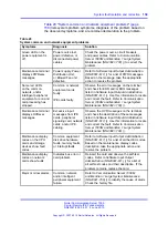
Page 157: ...using the diagnostic tools described in this chapter 1 Observe and list the problem symptoms the system is exhibiting Typical symptoms can be the Local Carrier Interface card or Remote Carrier Interface card has its red LEDs turned on the Remote Carrier Interface card faceplate display shows a fault code some common equipment or power supplies have their green LEDs turned off some of the common eq...

Page 158: ...e normal operation of Carrier Remote IPE are usually caused by faulty equipment accidental disconnection of cables improper environmental conditions Check the symptoms listed in Table 30 Carrier Remote IPE equipment problems page 160 that are related to problems with a previously operating Carrier Remote IPE System fault isolation and correction To isolate Carrier Remote IPE faults in the system f...

Page 159: ...stem Maintenance NN43021 700 Maintenance terminal displays OVDxxxx messages Excessive input messages from IPE cards peripheral signaling card network cards and or IPE cabling Observe the OVD messages on the terminal and check the description of these messages listed in Software Input Output Administration NN43001 611 Use this information to locate and correct the fault Refer to Communication Serve...

Page 160: ...rror messages related to the CRI page 187 in System messages page 187 to identify the HEX codes that indicate possible problems with the Carrier Remote IPE Table 30 Carrier Remote IPE equipment problems page 160 deals specifically with Carrier Remote IPE service problems To diagnose these problems the table refers to the test procedures in this manual that are most likely able to resolve these pro...

Page 161: ...ce card self test page 171 and Procedure 41 Performing the Remote Carrier Interface card loopback test page 173 to check tracking and loopback Also refer to Software Input Output Administration NN43001 611 for a list of codes Based on the maintenance display codes description take the appropriate action and resolve the problem Error messages printed on the MMI terminal or the TTY Hardware or softw...

Page 162: ...d by hardware faults incorrect configuration a disabled Local Carrier Interface card or continuity problems between the card and other network cards connected to the network bus To isolate and correct the Local Carrier Interface card related problems see Procedure 37 Checking the Local Carrier Interface card status page 163 Procedure 38 Performing the Local Carrier Interface card self test page 16...

Page 163: ... being checked The far end alarm does not show at the near end LD 32 NPR000 STAT sl CARR CALS TTSA NND SPARED 0 0 21 21 NO N A 1 0 21 21 NO N A 2 0 21 21 NO N A Note This example shows 3 primary carriers and no spare all carriers without alarm and are available for New Data Calls No calls in progress LD 32 NPR000 STAT sl CARR CALS TTSA NND SPARED 0 3 0 21 YES N A 1 0 21 21 NO N A 2 0 21 21 NO N A ...

Page 164: ...m status 0 means that the Alarm Level is 0 no alarm TTSA Timeslots currently available for voice and data Carrier 0 superloop timeslots 5 to 25 for T1 and 5 to 31 for E1 Carrier 1 superloop timeslots 37 to 57 for T1 and 37 to 63 for E1 carriers Carrier 2 superloop timeslots 69 to 89 for T1 and 69 to 95 for E1 carriers NND No New Data calls NO indicates new data calls are not disallowed that is MCA...

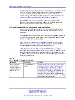
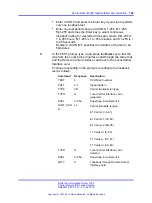
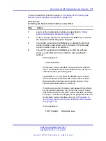
Page 165: ...terface card functions and outputs a fail or pass message after the test is completed To start the self test follow the steps in Procedure 38 Performing the Local Carrier Interface card self test page 165 Procedure 38 Performing the Local Carrier Interface card self test Step Action 1 Log in on the maintenance terminal as described in Using system maintenance programs page 154 2 At the prompt type...

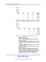
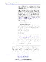
Page 166: ...f test and is faulty where xxxx can be one of the following values 0 ROM checksum failed 1 FLASH checksum failed 2 A21 1 faulty 3 A21 2 faulty 4 R71 faulty Replace the Local Carrier Interface card as described in Removing and replacing a Local Carrier Interface card page 182 NPRxxx message may be displayed as a result of a command activated self test if the Local Carrier Interface card is missing ...

Page 167: ...ecific timeslots that have to be assigned for the Carrier Remote IPE loopback testing The system loopback test also tests the superloop network switching functions and the peripheral controller loopback functions on the Local Carrier Interface card and the Remote Carrier Interface motherboards respectively The on line test 1 using the MMI command tests the loopback between the daughterboards of th...

Page 168: ...l Carrier Interface system loopback tests Step Action 1 Log in on the maintenance terminal as described in Using system maintenance programs page 154 2 At the prompt type LD 45 and press the Enter key to access the Background Signaling and Switching Program 3 Select test condition Nortel Communication Server 1000 Carrier Remote IPE Fundamentals NN43021 555 04 01 4 June 2010 Copyright 2007 2010 Nor...

Page 169: ...e Remote Carrier Interface card back to the Local Carrier Interface card Continue responding to the prompts to configure the loopback test as follows Command Response Description TEST 6 XCON test number PATT 0 7 Signal pattern TYPE CR Carrier transmission type TYPG N Local Carrier Interface card generator SUPL 0 252 Superloop in multiple of 4 SLOT_CAR R xx Carrier timeslots ranges E1 Carrier 0 5 3...

Page 170: ...n interface between the Local Carrier Interface card and the IPE cards housed in the Carrier Remote IPE module or cabinet Problems with the Remote Carrier Interface card can be caused by hardware faults incorrect configuration a disabled Remote Carrier Interface card or continuity problems between the card and IPE cards connected to the peripheral bus To isolate and correct the Remote Carrier Inte...

Page 171: ...or self test If the response is TEST PASSED the Remote Carrier Interface card passed the self test and is functional but must be enabled to turn off the red LED and to start processing calls Type ENXP x v and press the Enter key to enable the card and the associated IPE cards where x is the Remote Carrier Interface card number and v is the optional download software version v If the Remote Carrier...

Page 172: ... a pattern generator and detector The signal is transmitted by the Remote Carrier Interface card back to the Remote Carrier Interface card over a timeslot of a specified carrier Figure 25 Loopback path for XCON test 7 page 173 illustrates the loopback path and shows the Remote Carrier Interface card as a test pattern generator and detector To perform the Remote Carrier Interface card loopback test...

Page 173: ...st condition Enter XCON 0 and press the Enter key to perform only one loopback test Enter one test period shown in XCON H 1 255 M 1 255 Sþ1 255 and press the Enter key to select continuous loopback testing for a selected time span where Hþ1 255 is 1 to 255 hours M 1 255 is 1 to 255 minutes and S 1 255 is 1 to 255 seconds Example XCON M 5 specifies the duration of the test to be 5þminutes Nortel Co...

Page 174: ...inuity test If the results show BSDxxx messages refer to the list and description of these messages in Software Input Output Administration NN43001 611 The BSDxxx messages indicate the possible causes of the problem which should be checked to isolate the actual problem If the loopback continuity test passes the problem may be somewhere in the IPE cards 6 If the loopback continuity test fails repla...

Page 175: ...Type in the password 2 Type D S to display near end carrier status Type D S D to display far end carrier status The response is displayed on the screen and shows the firmware version present time and date individual carrier fault threshold parameters and the present status of each carrier link Example CRI D S CRI Remote IPE S N Software Version x xx mm dd yy hh mm Remote Site In Alarm State NO car...

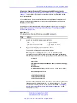
Page 176: ...splay Performance for near end or D P D Display Performance Distant for the far end carrier performance status using the MMI terminal To obtain the carrier link performance status follow the steps in Procedure 43 Checking the carrier performance status page 176 Procedure 43 Checking the carrier performance status Step Action 1 Log in on the maintenance terminal as described in Using system mainten...

Page 177: ...ecified thresholds Clear the cumulative error counter by executing the C E and C E D commands This error clearing does not affect the errored second counters 3 To display a similar report for the 24 hour period listed in 1 hour increments execute the D H Display History for the near end or D H D Display History Distant for the far end CRI D H Which Carrier 0 1 or 2 1 IPE Interface History Performa...

Page 178: ... tests Step Action 1 Execute the S C command to disable the desired primary carrier This command allows the calls in progress to complete before the carrier can be disabled The MMI terminal displays the following screen to enable a change in carrier status To disable carrier 1 set Equipped carrier 1 parameter to N CRI S C To set carrier parameters Equipped carrier 0 Yes or No Y Enable carrier 0 En...

Page 179: ...ing communication over this carrier Don t test a carrier in alarm condition using Test 1 it may disrupt traffic for the duration of the test A better approach is to disable the carrier you wish to test and perform one of the other tests to determine where the problem lies Disabling a carrier will prevent any new calls being placed over that carrier however it will not effect calls in progress over...

Page 180: ...r is operational if no additional errors are detected The STOP command terminates a test prematurely however it does not terminate the remote loopback during carrier Test 3 and can interrupt the traffic for several seconds If the STOP command causes a problem execute Test 3 again with 0 duration to undo the far end loopback or do not use the STOP command on Test 3 Test 5 places the carrier in the ...

Page 181: ...ck the results of the test and correct the identified fault 4 Replace the faulty card or fix the problem in the carrier link if this is indicated in the test report End Replacing Carrier Remote IPE cards If after completing troubleshooting it is determined that one or more Carrier Remote IPE cards are defective remove the defective cards and replace them with spares When inserting a spare Local Ca...

Page 182: ...g off the power to the module or cabinet This feature allows the system to continue normal operation when replacing a Local Carrier Interface card in the system or a Remote Carrier Interface card in the Remote IPE module or cabinet Removing and replacing a Local Carrier Interface card To remove and replace a Local Carrier Interface card follow the steps in Procedure 46 Removing and replacing a Loc...

Page 183: ...ly into the module If the problem persists troubleshoot or replace the Local Carrier Interface card 10 Connect the cable to the Local Carrier Interface card faceplate connector 11 Set the ENB DIS switch to ENL If the uppermost red LED on the Local Carrier Interface card faceplate turns off the card is functioning correctly and is enabled The outcome of the self test is indicated on the system term...

Page 184: ...ly against the faceplate to latch the card inside the module The Remote Carrier Interface card automatically starts the self test 8 Observe the red LED on the front panel during the self test If it flashes three times and stays on it has passed the test Go to step 9 If it does not flash three times and then stays on it has failed the test Pull the card partially out of the module and reinsert it f...

Page 185: ...E cabinet 3 Terminate your session with the system by logging out on your maintenance terminal by typing LOGO at the prompt dot prompt and pressing the Enter key If using the MMI terminal log out to complete the test and troubleshooting session End Packing and shipping defective cards To ship a defective card to a Nortel repair center follow the steps in Procedure 49 Packing and shipping defective...

Page 186: ...hipping and cost information from Nortel and mail the package to an authorized repair center End Nortel Communication Server 1000 Carrier Remote IPE Fundamentals NN43021 555 04 01 4 June 2010 Copyright 2007 2010 Nortel Networks All Rights Reserved ...

Page 187: ... the request of disable enable the RTE superloop Ensure that the LCI is installed and that the ENL DIS switch is in ENL position NWS0019 LCI did not respond to the request of disable enable the superloop Ensure that the LCI is installed and that the ENL DIS switch is in ENL position PWRxxxx Carrier Remote IPE cabinet system monitor emulation SCH6575 REM_IPE package is not equipped SCH6576 Missing ...

Page 188: ...m Level 2 Bit error rate exceeded CRI2130 Remote Carrier 1 Alarm Level 3 Bit error rate exceeded CRI2210 Remote Carrier 2 Alarm Level 1 Bit error rate exceeded CRI2220 Remote Carrier 2 Alarm Level 2 Bit error rate exceeded CRI2230 Remote Carrier 2 Alarm Level 3 Bit error rate exceeded Frame slip error code description CRI1031 Local Carrier 0 Alarm Level 3 Frame slip threshold exceeded CRI1131 Loca...

Page 189: ...Remote Carrier 2 Alarm Level 3 Out of frame Operation within threshold message description CRI1005 Local Carrier 0 Alarm Level 0 Within threshold CRI1105 Local Carrier 1 Alarm Level 0 Within threshold CRI1205 Local Carrier 2 Alarm Level 0 Within threshold CRI2005 Remote Carrier 0 Alarm Level 0 Within threshold CRI2105 Remote Carrier 1 Alarm Level 0 Within threshold CRI2205 Remote Carrier 2 Alarm L...

Page 190: ...B 05 A31 1 internal TXVM memory 06 A31 1 configuration memory 07 A31 1 external FIFO 08 A31 2 external buffer 09 A31 2 internal context memory phase A 0A A31 2 internal context memory phase B 0B A31 2 internal TXVM memory 0C A31 2 configuration memory 0D A31 2 external FIFO 0E A31 1 Peripheral side W72 loopback test 0F A31 2 Peripheral side W72 loopback test 10 R72 N P switching control memory 11 ...

Page 191: ... shelf test 1E End of test 1F R72 2 N P quiet code register test EE Bus error exception errors etc Note After PSDL the display on the Carrier Remote Interface card alternates between Peripheral Controller ID and the carrier 0 indicating that the clock reference is being received from carrier 0 Nortel Communication Server 1000 Carrier Remote IPE Fundamentals NN43021 555 04 01 4 June 2010 Copyright ...

Page 192: ...192 System messages Nortel Communication Server 1000 Carrier Remote IPE Fundamentals NN43021 555 04 01 4 June 2010 Copyright 2007 2010 Nortel Networks All Rights Reserved ...

Page 193: ... service and state tariffs Regulatory notices Notice for United States installations Carrier Remote IPE equipment complies with Part 68 of the United States Federal Communication Commission FCC rules On the rear of the pedestal unit of the switching equipment cabinet is a label that contains among other information the FCC registration numbers and ringer equivalence number REN for this equipment I...

Page 194: ...t your distributor please call Nortel Inc 2221 Lakeside Drive Richardson TX 75082 at 1 800 328 8800 If the trouble is causing harm to the telephone network the telephone company may request you to remove the equipment from the network until the problem is resolved There is no user repair involved with this equipment The equipment cannot be used on public coin service provided by the telephone comp...

Page 195: ...51 NT7R52 6 0P N A M 04DU9 1KN NT7R51 NT7R52 6 0P N A M 04DU9 1SN NT7R51 NT7R52 6 0P N A Note Digital Interfaces represent the Facility Interface Codes FIC Notice for Canadian installations CS 1000M and Meridian 1regulatory labels include Department of Communication CS03 332 404 A The Canadian Department of Communication label identifies certified equipment This certification means that the equipm...

Page 196: ...e the telecommunications company cause to request the use to disconnect the equipment Users should ensure for their own protection that the electrical ground connections of the power utility telephone lines and internal metallic water pipe system if present are connected together This precaution may be particularly important in rural areas DANGER DANGER OF ELECTRIC SHOCK Users should not attempt t...

Page 197: ...s appendix provides connection diagrams and pin assignment information for all connectors interfacing with external equipment Nortel Communication Server 1000 Carrier Remote IPE Fundamentals NN43021 555 04 01 4 June 2010 Copyright 2007 2010 Nortel Networks All Rights Reserved ...

Page 198: ...connectors pin assignment Figure 26 Single LCI connection diagram local site connections Nortel Communication Server 1000 Carrier Remote IPE Fundamentals NN43021 555 04 01 4 June 2010 Copyright 2007 2010 Nortel Networks All Rights Reserved ...

Page 199: ...s 199 Figure 27 Multiple LCIs connection diagram local site daisy chain connection Nortel Communication Server 1000 Carrier Remote IPE Fundamentals NN43021 555 04 01 4 June 2010 Copyright 2007 2010 Nortel Networks All Rights Reserved ...

Page 200: ...s pin assignment Figure 28 Remote Carrier IPE module connection diagram single RCI configuration Nortel Communication Server 1000 Carrier Remote IPE Fundamentals NN43021 555 04 01 4 June 2010 Copyright 2007 2010 Nortel Networks All Rights Reserved ...

Page 201: ...201 Figure 29 Remote Carrier IPE cabinet connection diagram single RCI configuration Nortel Communication Server 1000 Carrier Remote IPE Fundamentals NN43021 555 04 01 4 June 2010 Copyright 2007 2010 Nortel Networks All Rights Reserved ...

Page 202: ...x T1 E1 Carrier Receive Tip from net 2 RRINGx T1 E1 Carrier Receive Ring from net 3 N C No connection 4 TRINGx T1 E1 Carrier Transmit Ring to net 5 TTIPx T1 E1 Carrier Transmit Tip to net Note The cable that connects to this connector is provided in the NT7T87AA T1 CSU Cable Kit The cable is a straight through cables between the Carrier Remote IPE 8 pin modular jack and the Telco demarcation point...

Page 203: ...end of the cable Table 35 NT7R58AA Maintenance Panel 6 pin modular jack system monitor pin assignment for J5 and J6 connectors System Monitor 6 Pin Modular Jack Pinouts 8 Pin Modular Jack Signal Name Signal Description J5 1 N C No connection J5 2 XSTXB Transmit NEGATIVE J5 3 XSTXA Transmit POSITIVE J5 4 XSRXB Receive NEGATIVE J5 5 XSRXA Receive POSITIVE J5 6 N C No connection J6 1 N C No connectio...

Page 204: ...rt 7 P1 7 P2 P3 Pin 9 REQB Request from SDI Port 8 N C N C N C No connection 9 N C N C N C No connection P2 4 to P2 6 DTR DSR Pins connected with 30 AWG wire Table 37 NT7R61 Remote Maintenance Panel maintenance port DB 9 male connector pin assignment DB 9 Remote Maintenance Connector Pinouts DB 9 Connector Pins Signal Name Signal Description 1 N C No connection 2 SDITX SDI Transmit 3 SDIRX SDI Rec...

Page 205: ...urn Green P1 7 ALM2 Customer External Alarm Input 2 Brown P1 8 N C No connection N C P1 9 N C No connection N C P1 10 GND Ground Return See Note P1 11 ALM1 Customer External Alarm Input 1 Blue P1 12 ALM3 Customer External Alarm Input 3 White Blue P1 13 N C No connection N C P1 14 N C No connection N C P1 15 N C No connection N C Note This connection is jumpered to pin 6 inside the P1 DB 15 connect...

Page 206: ...ound Return See Note 1 P1 11 ALM1 Customer External Alarm Input 1 5 V Blue P1 12 ALM3 Customer External Alarm Input 3 5 V White Blue P1 13 BTRN Battery Return for PFTU Orange P1 14 N C No connection N C P1 15 N C No connection N C Note This connection is jumpered to pin 6 inside the P1 DB 15 connector hood This connector is used to connect the NT7R87AA T1 CSU Cable Kit Table 40 Local and Remote Ca...

Page 207: ...ansmit Tip to network Note If the carrier links are just hardwired without using Telco T1 or E1 carrier links the 8 pin modular plug pins 2 and 1must be turned over swapped with pins 4 and 5 at one end However if using a T1 or an E1 Telco network the network provides that turnover Figure 31 RJ 48 type 8 pin modular plug pin assignments page 208 shows the 8 pin modular plug pin positions from left ...

Page 208: ...straight through wired when the color coded wires are in the same pin position for both 8 pin modular plugs For flat silver satin cable verify straight through wiring when plug at one end faces up and at the other end faces down Also verify that pins 1 2 4 and 5 are wired at both ends Nortel Communication Server 1000 Carrier Remote IPE Fundamentals NN43021 555 04 01 4 June 2010 Copyright 2007 2010...

Page 209: ... Carrier Remote IPE capacity 35 CPU functions 24 functional architecture 21 IPE functions 25 local site hardware 12 network functions 24 related documentation 19 35 remote site hardware 12 site planning 46 carrier cable requirements 48 environmental requirements 46 47 power requirements 47 48 system overview 11 system selection 45 configuration carrier interface cards 114 115 MMI port 120 121 over...

Page 210: ...a 33 L LD 11 155 LD 17 116 117 150 LD 22 115 LD 32 118 119 150 154 165 171 LD 45 150 152 168 173 LD 97 118 Local Carrier Interface cards 12 18 21 26 affecting system capacity 35 carrier interface 29 CPU to MPU bus interface 29 ENB DIS switch 146 147 182 fault isolation and correction 162 165 167 functions 27 installation of faceplate cables 69 70 installation on local system 67 installation on loc...

Page 211: ...e cards 19 21 26 Card LAN interface 33 carrier interface 34 fault isolation and correction 170 171 173 functions 30 32 HEX codes 190 IPE interface 33 LEDs 146 147 maintenance commands 151 memory 33 MPU Micro Processing Unit 32 replacing 183 Remote IPE modules installing cards in 86 87 linked to local system 17 remote sites cabling 18 hardware 14 replacing Carrier Remote IPE cards Local Carrier Int...

Page 212: ...s 150 V voice call tests 136 W wall mounted Carrier Remote IPE installation attendant console 113 cabinets 20 98 101 cabling 19 carrier span connection 106 I O panel assembly 104 IPE cards into cabinets 104 105 PTFU Power Fail Transfer Unit 113 114 TTY and subscriber loop cables 108 wiring for T1 carrier links 17 36 37 48 pre installation setup 58 Nortel Communication Server 1000 Carrier Remote IP...

Page 213: ......
Page 214: ...herwise expressly agreed to in writing NORTEL PROVIDES THIS DOCUMENT AS IS WITHOUT WARRANTY OR CONDITION OF ANY KIND EITHER EXPRESS OR IMPLIED The information and or products described in this document are subject to change without notice Nortel Nortel Networks the Nortel logo and the Globemark are trademarks of Nortel Networks All other trademarks are the property of their respective owners To pr...

Reviews: