
11-30
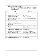
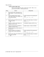
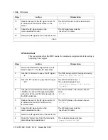
DRU tests
411-2051-500
Draft
00.01
November 1999
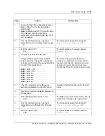
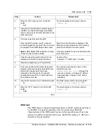
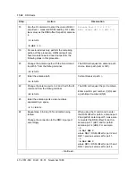
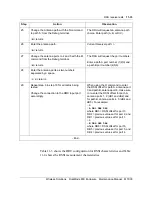
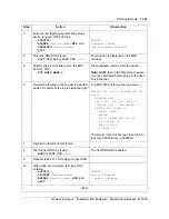
Step
Action
Observation
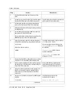
1
Put the DRU under test out of service at the
MTX.
2
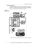
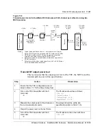
Connect a low loss RF cable from the IFR output
Duplex 65W Max jack to the RMC input port A.
The RF cable loss should be known and
will be used for calculation later.
3
Connect the interface terminal to the RS-232
port on the front panel of the TRU under test.
4
Place the transceiver in Debug mode by pressing
the BREAK key.
5
On the Debug terminal type “
SET FS ON
” and
type press the <RETURN> key.
If the command is not issued right-a-way then the
BREAK key may have to be typed again.
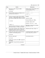
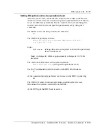
6
From the terminal, select the channel assigned
to the DRU under test by using the B command.
>B
<return>
Enter the channel number
>XXXX
The DRU will request a channel number
( 1…799 or 991…1023 )
On a successful channel change, the
Channel
and
Synth Lock
fields will
be updated:
Channel: xxxx
(DRU channel
number indicated)
Synth Lock: YES
(Sync Lock
changes to ‘YES’)
7
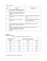
Ensure that the DRU configurations are as listed
in Table 11-3 for the RSSI characteristics test.
8
On the communications monitor, set the receiver
RF frequency to the frequency corresponding to
that of the TRU under test.
For an IFR 1600, by selecting the
transmitter frequency, the receiver
frequency will automatically be set.
9
Using the communications monitor, apply a -60
dBm on-channel RF signal modulated with a
1kHz tone at ±2.9 kHz deviation to the DRU
under test.
10
Use the P command to measure the RSSI signal
reading.
>P
<return>
The DRU will prompt for the
measurement to query:
Enter R, SAT, ST, or A
- continued -
Summary of Contents for DualMode 800
Page 2: ......
Page 4: ......
Page 6: ...vi Publication history Nortel Networks Confidential 411 2051 500 Draft 00 01 November 1999...
Page 82: ...2 20 Periodic maintenance 411 2051 500 Draft 00 01 November 1999...
Page 90: ...3 8 Test equipment and precautions 411 2051 500 Draft 00 01 November 1999...
Page 100: ...5 6 Master Oscillator tests 411 2051 500 Draft 00 01 November 1999...
Page 106: ...6 6 Antenna and transmission line tests 411 2051 500 Draft 00 01 November 1999...
Page 116: ...8 4 Alarm Control Unit ACU tests 411 2051 500 Draft 00 01 November 1999...
Page 138: ...10 2 ICRM tests 411 2051 500 Draft 00 01 November 1999...
Page 200: ...12 10 Enclosure maintenance 411 2051 500 Draft 00 01 November 1999...
Page 208: ...A 8 Appendix A Frequency table 411 2051 500 Draft 00 01 November 1999...
Page 215: ......


