

11-48
DRU tests
411-2051-500
Draft
00.01
November 1999
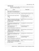
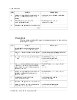
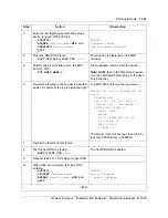
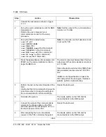
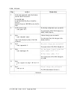
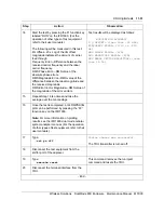
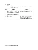
Step
Action
Observation
1
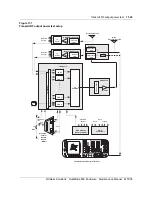
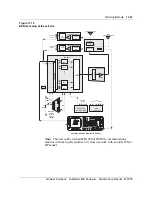
Connect the test setup as shown in Figure
11-10.
2
Set up the communications monitor for BER
measurement.
Refer to the user’s manual of your
communications monitor for the setup
procedure.
Note:
Set the output of the communications
monitor to -110 dBm.
3
Set up the TRU as listed below:
>set LT off
>set PATYPE NONE
>set PERS TTC
>set CHANNEL xxxx
(the B command)
>set TXPOWIDX 0
(the E command)
>set BCH loop off
(the J command)
>set RF loop on
(the J command)
>set PA on
(the C command)
Note:
You can also use the Fullscreen mode
to set up the TRU.
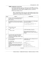
4
Press the appropriate key (for example: GO,
START) on the communications monitor to
begin the BER test.
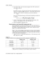
The bit error rate must be less than 3% when
output level of the communications monitor is
at -110 dBm.
Record the test result when the PRBS (Total
bits generated) reaches around 1,000,000
bits.
If BER is out of specifications, replace the
TRU and perform the test again. If problem
persists, perform troubleshooting.
5
Perform the test on the other timeslots of the
TRU.
Use the Set Slot (H) command to change the
slots. Remember to change the settings on
the communications monitor accordingly.
Record the test result.
6
Normalize the system.
The A-side splitter on the TRU shelf is
connected back to the RMC output.
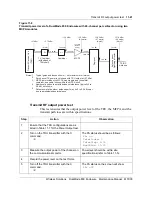
7
Connect the output of the communications
monitor to the B-side splitter on the TRU
shelf and perform the test (Steps 2 to 5) on
the B-side receiver of the TRU.
Record the test result.
8
After completing the test on the B-side
receiver of the TRU, normalize the system.
The B-side splitter on the TRU shelf is
connected back to the RMC output.
- End -
Summary of Contents for DualMode 800
Page 2: ......
Page 4: ......
Page 6: ...vi Publication history Nortel Networks Confidential 411 2051 500 Draft 00 01 November 1999...
Page 82: ...2 20 Periodic maintenance 411 2051 500 Draft 00 01 November 1999...
Page 90: ...3 8 Test equipment and precautions 411 2051 500 Draft 00 01 November 1999...
Page 100: ...5 6 Master Oscillator tests 411 2051 500 Draft 00 01 November 1999...
Page 106: ...6 6 Antenna and transmission line tests 411 2051 500 Draft 00 01 November 1999...
Page 116: ...8 4 Alarm Control Unit ACU tests 411 2051 500 Draft 00 01 November 1999...
Page 138: ...10 2 ICRM tests 411 2051 500 Draft 00 01 November 1999...
Page 200: ...12 10 Enclosure maintenance 411 2051 500 Draft 00 01 November 1999...
Page 208: ...A 8 Appendix A Frequency table 411 2051 500 Draft 00 01 November 1999...
Page 215: ......


