

Nortel Networks Confidential
Alarm Control Unit
1-5
Wireless Solutions
DualMode 800 Enclosure Maintenance Manual
MTX08
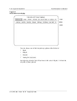
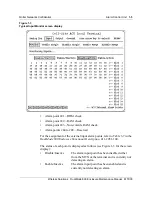
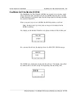
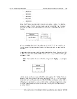
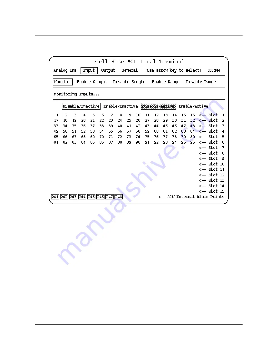
Figure 1-3
Typical Input Monitor screen display
•
Alarm point 241—ROM check
•
Alarm point 242—RAM check
•
Alarm point 243—Non-volatile RAM check
•
Alarm points 244 to 248—Reserved
For the assignment of the external input alarm points, refer to Table 3-7 in the
DualMode 800 Enclosure Functional Description, 411-2051-100.
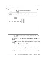
The status of each point is displayed as follows (see Figure 1-3 for the screen
display):
•
Disable/Inactive
The alarm input point has been disabled either
from the MTX or the terminal and is currently not
detecting an alarm.
•
Enable/Inactive
The alarm input point has been enabled and is
currently not detecting an alarm.
Summary of Contents for DualMode 800
Page 2: ......
Page 4: ......
Page 6: ...vi Publication history Nortel Networks Confidential 411 2051 500 Draft 00 01 November 1999...
Page 82: ...2 20 Periodic maintenance 411 2051 500 Draft 00 01 November 1999...
Page 90: ...3 8 Test equipment and precautions 411 2051 500 Draft 00 01 November 1999...
Page 100: ...5 6 Master Oscillator tests 411 2051 500 Draft 00 01 November 1999...
Page 106: ...6 6 Antenna and transmission line tests 411 2051 500 Draft 00 01 November 1999...
Page 116: ...8 4 Alarm Control Unit ACU tests 411 2051 500 Draft 00 01 November 1999...
Page 138: ...10 2 ICRM tests 411 2051 500 Draft 00 01 November 1999...
Page 200: ...12 10 Enclosure maintenance 411 2051 500 Draft 00 01 November 1999...
Page 208: ...A 8 Appendix A Frequency table 411 2051 500 Draft 00 01 November 1999...
Page 215: ......


