


12-8
Enclosure maintenance
411-2051-500
Draft
00.01
November 1999
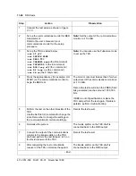
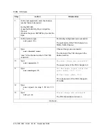
Follow the procedure when replacing a TRU:
1. At the MTX, put the affected channel(s) out-of-service.
2. Loosen the tab at the top edge of the TRU and move it away from the
TRU.
3. Using the handle on the front of the TRU, gently pull the module out of
the backplane connector and then slide it out of the shelf.
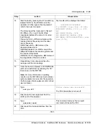
4. Place the replacement unit in the shelf guides.
5. Slide the unit into the shelf until it reaches the backplane connector.
6. Line up the TRU connector with the backplane connector and carefully
mate the connectors. Do not force the module into the shelf. If this is not
done with care, the pins of the connector may be damaged.
7. Move the tab over the top edge of the TRU and tighten the tab.
8. Perform the operational checks on the TRU.
9. At the MTX, put the channel/DRU in-service.
10. Perform a call through test on the TRU replaced. It may be necessary to
make several calls before the system selects the channel number assigned
to the DRU.
Replacing the
MCPA module
The channels associated with the Multi-Channel Power Amplifier (MCPA)
module should be out-of-service during the off-line replacement. This is of
major significance if it is supporting the control channel of the site/sector. In
that case, ensure the system switches to a back-up channel.
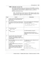
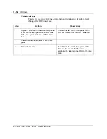
Follow the procedure when replacing a MCPA:
1. At the MTX, put the affected channels out-of-service.
2. Turn the RF ON switch on the front panel of the MCPA module to OFF.
3. Switch off the circuit breaker of the MCPA module at the RIP.
4. Loosen the screws mounting the MCPA module to the MCPA shelf and
then remove the module from the shelf.
5. Replace a new or known working MCPA module on to the shelf and fix it
with the mounting screws.
6. Switch on the circuit breaker of the MCPA module at the RIP.
7. Turn the RF ON switch on the front panel of the MCPA module to ON.
8. Perform the operational checks on the MCPA.
9. At the MTX, put the affected channels in-service.
Summary of Contents for DualMode 800
Page 2: ......
Page 4: ......
Page 6: ...vi Publication history Nortel Networks Confidential 411 2051 500 Draft 00 01 November 1999...
Page 82: ...2 20 Periodic maintenance 411 2051 500 Draft 00 01 November 1999...
Page 90: ...3 8 Test equipment and precautions 411 2051 500 Draft 00 01 November 1999...
Page 100: ...5 6 Master Oscillator tests 411 2051 500 Draft 00 01 November 1999...
Page 106: ...6 6 Antenna and transmission line tests 411 2051 500 Draft 00 01 November 1999...
Page 116: ...8 4 Alarm Control Unit ACU tests 411 2051 500 Draft 00 01 November 1999...
Page 138: ...10 2 ICRM tests 411 2051 500 Draft 00 01 November 1999...
Page 200: ...12 10 Enclosure maintenance 411 2051 500 Draft 00 01 November 1999...
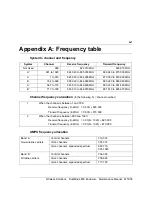
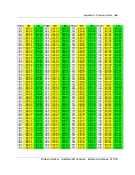
Page 208: ...A 8 Appendix A Frequency table 411 2051 500 Draft 00 01 November 1999...
Page 215: ......


