1-10
Equipment operation
Nortel Networks Confidential
411-2051-500
Draft
00.01
November 1999
Stand-alone mode operation
In stand-alone mode you can use the handset on the front panel of the DCSM
to originate and answer calls.
The mobile unit functions in the same way as a subscriber mobile telephone
in the cellular system. For this reason, the mobile unit in the DCSM has to be
activated in the same way as a subscriber mobile telephone. The cellular
system will not recognize the mobile unit or allow it to function unless the
programming on the Numerical Assignment Modules (NAM) is completed.
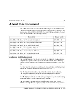
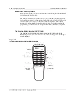
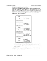
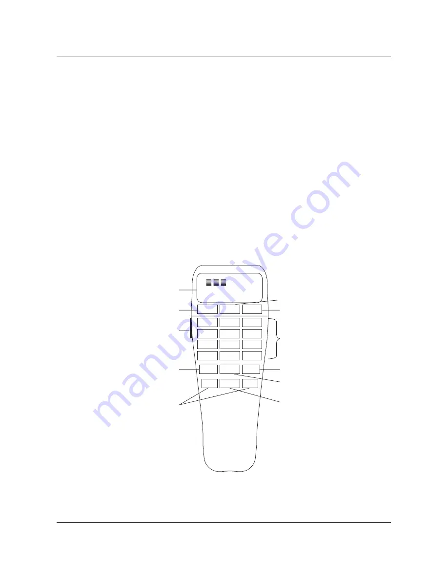
The Hughes M6200 handset (NT3P75AB)
The Hughes M6200 cellular telephone is used as the mobile unit in the
DCSM. Figure 1-5 shows the location of controls and keypad on the Hughes
M6200 handset.
Figure 1-5
Controls and keypad on Hughes M6200 handset
SND
PWR
END
1
2
3
4
5
6
7
8
9
*
0
#
RCL
CLR
STO
M1
FCN
M2
QZ
ABC
DEF
GHI
JKL
MNO
PRS
TUV
WXY
InUse
Roam
NoSvc
Digital
on
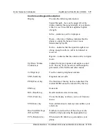
Display
Up/Down Volume
Control Button
Send Key
End Key
Power Key
Digit Keys
Clear Key
Store Key
Function Key
One-Touch
Dial Keys
Recall Key
M6200 Handset
Summary of Contents for DualMode 800
Page 2: ......
Page 4: ......
Page 6: ...vi Publication history Nortel Networks Confidential 411 2051 500 Draft 00 01 November 1999...
Page 82: ...2 20 Periodic maintenance 411 2051 500 Draft 00 01 November 1999...
Page 90: ...3 8 Test equipment and precautions 411 2051 500 Draft 00 01 November 1999...
Page 100: ...5 6 Master Oscillator tests 411 2051 500 Draft 00 01 November 1999...
Page 106: ...6 6 Antenna and transmission line tests 411 2051 500 Draft 00 01 November 1999...
Page 116: ...8 4 Alarm Control Unit ACU tests 411 2051 500 Draft 00 01 November 1999...
Page 138: ...10 2 ICRM tests 411 2051 500 Draft 00 01 November 1999...
Page 200: ...12 10 Enclosure maintenance 411 2051 500 Draft 00 01 November 1999...
Page 208: ...A 8 Appendix A Frequency table 411 2051 500 Draft 00 01 November 1999...
Page 215: ......


