
1-48
Equipment operation
Nortel Networks Confidential
411-2051-500
Draft
00.01
November 1999
Power setup procedure
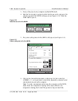
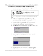
To set the MCPA output power, use the following procedure:
1. Run the ‘Nortel gain’ program by performing Steps 1 to 5 of the
procedure listed in the Running the MCPA software on the computer
section. The power setting menu will pop out (see Figure 1-11).
2. Enter the target output power and the number of channels supported by
the MCPA shelf in their respective areas on the menu.
3. Initialize the setting by clicking the Start Initialization menu bar. If the
Start Initialization bar is not active (grayed out) on the menu, re-entering
the output power level will bring it on (active) again.
4. A prompt requiring that all carriers are on will appear. Make sure that the
number of turned-on carriers (TRUs) matches the number of channels
entered. Click ‘OK’.
5. At the ‘Initialization Done’ prompt, click ‘OK’. Power set up is
complete.
IMPORTANT
Nortel Networks recommends that ALL channels (with at least
eight channels) be turned on at the time of initial power
setting. Otherwise, accuracy of the output power may be
affected.
IMPORTANT
Suppose that your cell/sector is using 16 channels at the time
of the power set up and you plan to expand it to 24 channels in
the future. You can enter 24 as your number of channels for the
cell/sector. However, for output accuracy, you should have all
24 channels turned on at the time of initialization. If you do not
have the eight expansion channels ready, it is best to keep the
number of channels to 16 at this time and perform
initialization again at the time when the cell/sector expands to
24 channels.
Summary of Contents for DualMode 800
Page 2: ......
Page 4: ......
Page 6: ...vi Publication history Nortel Networks Confidential 411 2051 500 Draft 00 01 November 1999...
Page 82: ...2 20 Periodic maintenance 411 2051 500 Draft 00 01 November 1999...
Page 90: ...3 8 Test equipment and precautions 411 2051 500 Draft 00 01 November 1999...
Page 100: ...5 6 Master Oscillator tests 411 2051 500 Draft 00 01 November 1999...
Page 106: ...6 6 Antenna and transmission line tests 411 2051 500 Draft 00 01 November 1999...
Page 116: ...8 4 Alarm Control Unit ACU tests 411 2051 500 Draft 00 01 November 1999...
Page 138: ...10 2 ICRM tests 411 2051 500 Draft 00 01 November 1999...
Page 200: ...12 10 Enclosure maintenance 411 2051 500 Draft 00 01 November 1999...
Page 208: ...A 8 Appendix A Frequency table 411 2051 500 Draft 00 01 November 1999...
Page 215: ......


