2-2
Periodic maintenance
411-2051-500
Draft
00.01
November 1999
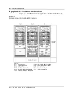
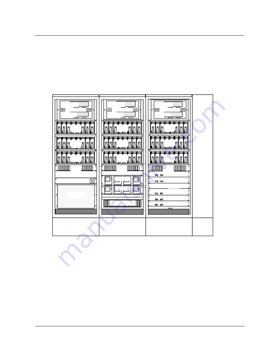
Equipment in a DualMode 800 Enclosure
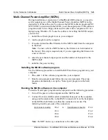
Figure 2-1 shows the location of equipment in a DualMode 800 Enclosure.
Figure 2-1
Equipment layout of a DualMode 800 Enclosure
Bay 1
Bay 2
Bay 3
Interface
Module
ICRM
RIP1
RIP2
RIP3
DCSM
ACU
HSMO
ERMC1
ERMC2
ERMC3
CSU
DCLC
Battery Pedestal
Rectifiers
Rectifiers
PCS
1
25
33
41
26
31 32
49 50
55 56
40
57
65
64
72
48
9
17
2
7 8
16
24
4
5
1
8
TRU
Shelf1
TRU
Shelf2
TRU
Shelf3
TRU
Shelf4
TRU
Shelf5
TRU
Shelf6
TRU
Shelf7
TRU
Shelf8
TRU
Shelf9
MCPA1
MCPA2
MCPA3
MCPA4
MCPA5
MCPA6
MCPA Shelf1
MCPA Shelf2
MCPA Shelf3
Legends:
ACU
Alarm Control Unit
HSMO
High Stability Master Oscillator
CSU
Channel Service Unit
MCPA
Multi-Channel Power Amplifier
DCLC
DC Load Center
PCS
Power Control Shelf
DCSM
DualMode Cell Site Monitor
RIP
Rack Interface Panel
ERMC
Enhanced Receive MultiCoupler
TRU
Transmit Receive Unit
ICRM
Integrated Cellular Remote Module
Summary of Contents for DualMode 800
Page 2: ......
Page 4: ......
Page 6: ...vi Publication history Nortel Networks Confidential 411 2051 500 Draft 00 01 November 1999...
Page 82: ...2 20 Periodic maintenance 411 2051 500 Draft 00 01 November 1999...
Page 90: ...3 8 Test equipment and precautions 411 2051 500 Draft 00 01 November 1999...
Page 100: ...5 6 Master Oscillator tests 411 2051 500 Draft 00 01 November 1999...
Page 106: ...6 6 Antenna and transmission line tests 411 2051 500 Draft 00 01 November 1999...
Page 116: ...8 4 Alarm Control Unit ACU tests 411 2051 500 Draft 00 01 November 1999...
Page 138: ...10 2 ICRM tests 411 2051 500 Draft 00 01 November 1999...
Page 200: ...12 10 Enclosure maintenance 411 2051 500 Draft 00 01 November 1999...
Page 208: ...A 8 Appendix A Frequency table 411 2051 500 Draft 00 01 November 1999...
Page 215: ......


