background image

Documentation Release Note

Number: MER-1002-003

No

r

tel Networks 11/4/02 3 of 26


TM 

Preparing for installation

The procedures in this section are for systems that have already been 
upgraded to the Fiber Network. Follow the procedures in order.

Verifying removal of 3PE cards from Option 81 Core shelves

In Option 81 systems, the 3PE card must be removed from the Core shelves. 
This card should have been removed during the upgrade procedure. If this 
card was not removed during the upgrade process, remove it now.

Note: This procedure is for Option 81 systems with Core shelves. This 
procedure is NOT necessary for Option 81C systems with Core/Net 
shelves.

Procedure 1
Removing the 3PE card from both Cores:

1

In Core 1, hardware disable the 3PE card.

2

In Core 0, hardware disable the 3PE card.

3

Remove the 3PE faceplate cable.

4

Remove the 3PE cards from Core 1 and 0.

—————————— End of Procedure ——————————

Add the new Network modules

The new Network modules must be connected to the system. Follow the 
instructions in 

System Installation Procedures

 (553-3001-210) to correctly 

configure the power and System Monitor connections.

Add CNI cards if necessary

CNI-3 cards are added only if additional ports are required. CNI-3 cards can 
only be installed in an 

inactive

 Core module.

Port assignments

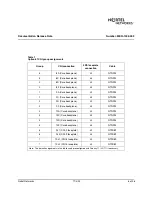
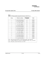
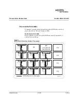
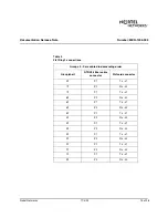
The default port assignments for CNI cards in Option 81 and 81C systems are 
shown in Table 1 and Table 2. These assignments can be modified in 
Overlay 17 if necessary.

Summary of Contents for MER-1002-003

Page 1: ...h FNF and include Option 81C CNI group assignments on a system that originated as a non FNF system prior to X11 Release 25 Correction Note Figure table procedure and page numbers for example Table 5 p...

Page 2: ...s if necessary 2 Pre routing CNI to 3PE cables 4 Pre route the FIJI cables 8 Installing cards in the Network modules 16 Installing and enable the 3PE cards 16 Installing and enabling the Peripheral Si...

Page 3: ...81C systems with Core Net shelves Procedure 1 Removing the 3PE card from both Cores 1 In Core 1 hardware disable the 3PE card 2 In Core 0 hardware disable the 3PE card 3 Remove the 3PE faceplate cabl...

Page 4: ...e faceplate disabled before installation 5 Faceplate enable all CNI cards on the inactive Core End of Procedure Procedure 3 Adding a CNI group 1 Add CNI group s 2 Software enable the original CNI port...

Page 5: ...te to the 3PE card with two NT9D89 cables When a CNI card is upgraded to a CNI 3 card the original NTND14 backplane cables are left in place only the NT9D89 CNI 3 to 3PE faceplate cables must be added...

Page 6: ...4 NTND14 1 9A Core backplane J3 NTND14 1 9C Core backplane J4 NTND14 2 9D Core backplane J3 NTND14 2 9F Core backplane J4 NTND14 3 10A Core backplane J3 NTND14 3 10C Core backplane J4 NTND14 4 10D Cor...

Page 7: ...e J3 NTND14 3 13C Core Net backplane J4 NTND14 4 13D Core Net backplane J3 NTND14 4 13F Core Net backplane J4 NTND14 5 13 J1 CNI 3 faceplate J3 NT9D89 5 13 J2 CNI 3 faceplate J4 NT9D89 6 14A Core Net...

Page 8: ...13D Core Net backplane J3 NTND14 3 13F Core Net backplane J4 NTND14 4 14A Core Net backplane J3 NTND14 4 14C Core Net backplane J4 NTND14 5 14D Core Net backplane J3 NTND14 5 14F Core Net backplane J...

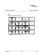
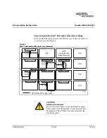
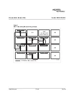
Page 9: ...helf 1 of each new Network Group Figure 1 Route FIJI to FIJI cables Option 81C example J3 J4 J3 J4 J3 J4 J3 J4 J3 J4 J3 J4 J3 J4 Tx J1 Rx J2 Group 0 shelf 0 Group 0 shelf 1 Tx J1 Rx J2 Group 2 shelf 0...

Page 10: ...Ring cable of the appropriate length from the FIJI card in shelf 0 of the current highest Network Group to the FIJI card in shelf 0 of the new Network Group 4 If more than one Network Group is to be...

Page 11: ...ptic cable Tx J1 Rx J2 Group 0 shelf 0 Group 0 shelf 1 Tx J1 Rx J2 Group 2 shelf 0 Tx J1 Rx J2 Group 2 shelf 1 Tx J1 Rx J2 Group 4 shelf 1 Tx J1 Rx J2 Group 4 shelf 0 Tx J1 Rx J2 Group 3 shelf 0 Tx J1...

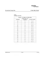
Page 12: ...ns Groups X 0 are cabled in ascending order Group shelf NTRC48 fiber cable connector FIJI card connector 0 0 P1 Tx J1 1 0 P2 Rx J2 1 0 P1 Tx J1 2 0 P2 Rx J2 2 0 P1 Tx J1 3 0 P2 Rx J2 3 0 P1 Tx J1 4 0...

Page 13: ...N Damage to Equipment Do not excessively bend or cinch the Fiber Ring cables These cables are easily damaged Use the Optical Cable Management Card OCMC to manage and protect the Fiber Ring cables NTRC...

Page 14: ...NTRC48 FIJI Fiber Ring cable of the appropriate length from shelf 1 of the FIJI card in Group 0 to the FIJI card in the new highest Network Group shelf 1 4 Route a NTRC48 cable from the FIJI card in t...

Page 15: ...s Groups 0 X are cabled in descending order Group shelf NTRC48 fiber cable connector FIJI card connector 0 1 P1 Tx J1 7 1 P2 Rx J2 7 1 P1 Tx J1 6 1 P2 Rx J2 6 1 P1 Tx J1 5 1 P2 Rx J2 5 1 P1 Tx J1 4 1...

Page 16: ...Ring example NTRC48xx fiber optic cable Group 0 shelf 0 Group 0 shelf 1 Tx J1 Rx J2 Group 2 shelf 0 Group 2 shelf 1 Tx J1 Rx J2 Group 4 shelf 1 Tx J1 Rx J2 Group 4 shelf 0 Group 3 shelf 0 Group 3 she...

Page 17: ...ing the Conf TDS cards if necessary on page 19 End of Procedure Installing and enable the 3PE cards Three steps are required to install the 3PE cards Procedure 8 Installing and enabling 3PE cards 1 Ve...

Page 18: ...7 8 0 3PE cards connected to the a CNI in Core or Core Net 0 0 on on on on 1 on on off on 2 on off on on 3 on off off on 4 off on on on 5 off on off on 6 off off on on 7 off off off on 1 3PE cards co...

Page 19: ...abling and inserting the FIJI cards Procedure 10 Disabling and inserting FIJI cards 1 Faceplate disable the FIJI cards 2 Insert the FIJI cards into slots 2 and 3 of each new Network module Do not plug...

Page 20: ...d connected to the 3PE cards See Pre routing CNI to 3PE cables on page 5 2 Attach the cables to the inactive CNI cards See Table 1 Option 81 CNI group assignments on page 6 Table 2 Option 81C CNI grou...

Page 21: ...on each new FIJI card is disabled 2 Plug the FIJI cards into the Network module backplane Push the latches forward to lock the card in place 3 Enable the faceplate switch Note The card will not enabl...

Page 22: ...4 Connect new groups to the Fiber Network 1 In each new Network Group connect a NTRC47AA cable from J4 to J4 of the FIJI cards See Figure 5 LD 17 to load the program REQ CHG TYPE CEQU XCT xxx enter th...

Page 23: ...am LD 60 to load the program SSCK 0 to check if Clock 0 is active or standby SWCK to switch clocks if necessary to exit the program J3 J4 J3 J4 J3 J4 J3 J4 J3 J4 J3 J4 J3 J4 NTRC47AA FIJI to FIJI cabl...

Page 24: ...rom Group 0 P1 to the current highest Network Group P2 9 Attach the new Shelf 1 Fiber Ring cables in the correct configuration 10 Verify that the Rings are in Survival State and FIJI cards are enabled...

Page 25: ...ted as a non FNF system prior to X11 Release 25 on page 8 for slot and Group assignments 14 Plug in the Conf TDS cards Push the latches forward to lock the card in place 15 Faceplate enable the Conf T...

Page 26: ...ks 11 4 02 26 of 26 TM Projected Inclusion in NTP This correction will be included in the next standard release of Meridian 1 documentation Nortel Networks the Nortel Networks logo the Globe mark SL 1...

Reviews: