background image

 Chapter 25 — Fault locating and clearing

Page 501 of 536

Option 11C Compact

Planning, Installation, Fault Clearing and CCBR Guide

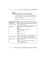
Possible cause

Action

If the PE circuit 
card is in an 
expansion cabinet, 
the fiber optic 
cable may be 
defective 

Note: Call processing for the Expansion cabinet is interrupted while the 

Fbr Rcvr card

 is being replaced.

Disable the Expansion cabinet by entering:
LD 32
DISS 1

Disable the Fiber Link by entering:
LD 135
DIS FIL 1

Replace the fiber optic cable.

Perform Local and Remote Loop-back tests on the link by entering:
LD 135
LLBK FIL 1
RLBK FIL 1

Enable the Fiber Link by entering:
LD 135
ENL FIL 1

Enable the Expansion cabinet by entering:
LD 32
ENLS 1

Enable the circuit card by entering
LD 32
ENLC c
(“c” represents the card number)

Test the circuit card by entering
LD 30
TEST
(the TEST command ensures that all circuit cards are re-enabled in the 
expansion cabinet)

—continued—

Summary of Contents for Meridian Meridian 1

Page 1: ...serves the right to make changes in design or components as progress in engineering and manufacturing may warrant This equipment has been tested and found to comply with the limits for a Class A digital device pursuant to Part 15 of the FCC rules Meridian1 Option 11C Compact and Hospitality are trademarks of Nortel Northern Telecom This Nortel documentation is protected by copyright It may not be ...

Page 2: ...llation Fault Clearing and CCBR Guide Revision history January 1999 Issue 3 0 Standard Includes content for X27 Release 2 September 1998 Issue 2 0 Standard Includes content for Hospitality applications November 1997 Issue 1 0 Standard ...

Page 3: ...553 3121 210 Standard 3 0 January 1999 ...

Page 4: ...Design and architecture 1 Easy to install and program 1 Fully featured 3 Unique Option 11C Compact elements 3 Software Delivery card 3 Flash Drive 4 Software Daughterboard 4 Security Device 4 System specifications 4 Input Voltage 4 Number of Peripheral PE slots 5 Software generic 5 Conference channels 5 Intercabinet connection 5 Power Failure Transfer Unit PFTU 5 Reserve power 5 Hospitality applic...

Page 5: ...r card 16 Telephones and attendant console 16 Cables and wires 16 Miscellaneous items 18 Chapter 3 System and site requirements 19 Environmental requirements 19 Earthquake bracing requirements 20 Grounding requirements 21 Grounding requirements 22 Grounding method 24 Conduit requirements 24 Commercial power requirements 25 Optimal power installation 26 Alternative power installation 29 Auxiliary e...

Page 6: ...anada 52 United States 52 U S A and Canada Network connections 53 North American Numbering Plan 53 Equal Access 53 FCC compliance registered equipment for Direct Inward Dial DID calls 54 Radio and TV interference 56 Information for Canada 56 Chapter 5 Safety instructions 57 Symbols you should recognize 57 Safety instructions when installing telephone equipment 58 Safety instructions when using tel...

Page 7: ...vice panel 86 Cabinets powered by different service panels 86 Grounding instructions for cabinets 86 Chapter 11 Installing the power supply 89 General information 89 Power supplies 89 Switch settings 89 AC power supply installation 92 Chapter 12 Adding an expansion cabinet 95 General information 95 Cabinet configurations 95 Fiber optic equipment 95 Grounding 96 Power 96 Chapter 13 Installing the c...

Page 8: ... and Ethernet ports 125 General information 125 Modem setup requirements 126 Installing and connecting SDI ports 128 NTMW01 SSC 128 NTMW10 Fiber Receiver card 130 Terminal setup 131 Installing and connecting an ethernet cable 135 Chapter 16 Starting up and testing the system 139 General information 139 Overview of Software Components 139 Software Daughterboard 139 Software Delivery PCMCIA Card 139...

Page 9: ...er 19 Connecting an external alarm 191 General information 191 Alarm port assigned in software 191 Chapter 20 Meridian Mail Compact Option installation and maintenance 193 General information 193 Installing the Meridian Mail Compact Option hardware 196 Precautions 196 Installing the RSM Assembly Module NTMW50AA 196 Installing the hard drive 197 Installing the daughterboards 199 Installing the Meri...

Page 10: ... rejected 222 Understanding the keycode label 223 Mail software installation 225 What to do before you begin 225 Performing a software installation 225 Defining Mail in the customer data block overlay 15 247 Meridian Mail Compact Option upgrade 251 What to do before you begin 251 Performing a comprehensive upgrade 251 Backing up the system 274 Scheduling backups 275 Restoring the system 276 The To...

Page 11: ...328 Introduction 328 How to restore a backed up database 328 Archiving and removing databases 337 Introduction 337 How to use archive feature 337 Installing an archived database 343 Introduction 343 How to install an archived database 343 Reviewing and clearing upgrade information 348 Introduction 348 How to review and clear upgrade information 348 Using the flash boot ROM utility 353 Introduction...

Page 12: ...ng plan 402 Extensions assigned differ from the default numbering plan 402 Changing the first number in the numbering plan 402 Changing the assignment of the first DN 403 Removing numbering plan interferences 423 Interference with ACD queues 423 Interference with Call Park extension numbers 423 Interference with SDI ports 424 Interference with the SPRE code 424 Interference with the attendant exte...

Page 13: ...ult locating and clearing 437 Precautions 437 General precautions 437 Fiber cable 438 Circuit cards 438 Communicating with the system 439 System terminal 439 Hardware maintenance tools 441 Circuit card features 442 Initialize button 445 System alarms 445 Software maintenance tools 448 Diagnostic programs 448 History File 451 End user reports 452 User report indications 452 Technical assistance ser...

Page 14: ...rcuit breaker on the power supply in the cabinet is on but all LEDs in the cabinet are off 473 Clearing Common Equipment faults 474 Common Equipment faults 474 Fault clearing procedures 474 Symptom Call processing stopped on the entire system 476 Symptom Fault indicated on the NTMW01 SSC card or Memory fault indicated 477 Symptom Fault indicated on the Tone and Digit Switch 479 Symptom Fault indic...

Page 15: ...runk cannot make or receive calls OVD message received 505 Symptom Trunk cannot make or receive calls no OVD message 508 Clearing attendant console faults 510 Attendant console faults 510 Fault clearing procedures 511 Symptom Console cannot make or receive calls OVD message received 512 Symptom Console cannot make or receive calls no OVD message 514 Symptom Indicator or digit display not functioni...

Page 16: ...nnot be heard 523 Symptom Noise or low volume on all calls 525 Symptom Defective indicator digit display or component 527 Symptom Defective feature 528 Symptom Defective add on module 529 Symptom Cannot dial from 2500 type telephone 530 Symptom No ring on 500 and 2500 type telephones 532 Final maintenance procedure 534 ...

Page 17: ...xiv Contents 553 3121 210 Standard 3 0 January 1999 ...

Page 18: ... describes the features limits and general design of the Meridian 1Option 11C Compact system Installation The installation portion of this guide describes how to install a new system how to add components to an existing system and how to upgrade software if required such as how to add TNs or change feature sets Fault Clearing The Fault Clearing portion of this guide describes how to locate and cle...

Page 19: ...uration Backup and Restore This guide provides information about Customer Configuration Backup and Restore including recommendations for performing backups and procedures for performing restores in situations where customer configuration information has been lost or corrupted ...

Page 20: ...pported by the Option 11C Compact system The maximum distance between the cabinets is 33 cable feet 10 cable meters Allow approximately 2 ft 0 5 m of slack at each end of the cable for routing inside the cabinets Call processing serial ports and network traffic are handled by an MC68040 processor located on the CPU card located in the main cabinet Easy to install and program The system is shipped ...

Page 21: ... over a modem connection Set Based Administration Set Based Administration is a feature that simplifies system installation and administration by enabling a telephone set to perform several administrative and maintenance procedures Examples such as changing data associated with specific set related features or changing Calling Party Name Display on a particular set can be performed through the Set...

Page 22: ...ation comes equipped standard with features such as Voice Menus and Automated Attendant Unique Option 11C Compact elements The Option 11C Compact system is characterized by the following unique elements Software Delivery card PCMCIA used for software up issues Flash Drives primary and backup Software Daughterboard Security Device which validates keycodes for features assigned to this system Softwa...

Page 23: ...n be retrieved and loaded into the system s active database Software Daughterboard The Software Daughterboard is used as a storage area for system and customer data It is also used to deliver and load the system software and customer data base in a new system installation Security Device The Security Device which is shipped with a new Option 11C Compact system is attached to the NTMW01 SSC card wh...

Page 24: ...ets are interconnected with a 10 m 33ft multi mode plastic fiber optic cable Note The A0632902 Plastic Fiber Optic Cable multi mode is the only fiber optic cable supported by the Option 11C Compact system The maximum distance between the cabinets is 33 cable feet 10 cable meters Allow approximately 2 ft 0 5 m of slack at each end of the cable for routing inside the cabinets Power Failure Transfer ...

Page 25: ...up that can be performed using LD 43 Customer data can be backed up from the database in use to the Primary Flash Drive the Backup Flash Drive or an external Software Delivery card PCMCIA Remote backup Remote backup can be performed with LD 143 using the Customer Configuration Backup and Restore CCBR feature The CCBR feature permits the user to backup customer configured data to an external IBM ty...

Page 26: ...abinet when used with the Option 11C Compact system or two Expansion cabinets when used with the Compact Hospitality system Expansion cabinet for Option 11C Compact One NTMW08 Cabinet can be used as an Expansion cabinet It provides six additional Peripheral Equipment PE slots Note In this case the expansion cabinet is the same cabinet type as the main cabinet Only one expansion cabinet can be used...

Page 27: ...ctors extend out of the bottom of the card cage in each cabinet The SDI connector in the main cabinet interfaces three SDI ports using a three port SDI cable In the expansion cabinet the SDI connector interfaces with one SDI port The Ethernet connector in the main cabinet provides a 10 Mbps Ethernet port Cooling Each cabinet is equipped with a cooling fan at the top of the cabinet Power supplies E...

Page 28: ...R Guide Figure 1 NTMW11 ac power supply Reserve power Reserve power can be provided by an Uninterruptible Power Supply UPS obtained locally The UPS provides a continuous AC power supply even during commercial power outages The UPS should be installed according to the manufacturer s instructions Power Supply Units ...

Page 29: ...ease 1 and NTDK81 for X27 Release 2 An NTDK22 Fiber Expansion Daughterboard interface Two PCMCIA interface slots Three SDI ports Conferencing Digitone Receiver Tone generation and tone detection functions Security Device socket Software Daughterboard System and customer data is stored on the Software Daughterboard attached to the SSC card The daughterboard also serves as a software delivery card f...

Page 30: ...ace The NTMW01 SSC card has a 2 slot PCMCIA interface socket located on its faceplate The socket can accommodate a Software Delivery card used primarily for software upgrades It can also be used for creating an external backup copy of the customer data base NTDK22 Fiber Expansion Daughterboard The Main cabinet can be connected to one or two expansion cabinets by mounting NTDK22 Fiber Expansion dau...

Page 31: ...Page 12 of 536 Chapter 2 Equipment identification 553 3121 210 Standard 3 0 January 1999 parity none odd even stop bits 1 2 data bits 7 8 The default settings are as shown in Table 1 ...

Page 32: ...he NTMW01 SSC card Conference capability is increased by 16 channels when a Fiber Expansion daughterboard is added to the SSC card to connect to an expansion cabinet Digitone Receiver tone generation tone detection functions The NTMW01 SSC card provides 30 channels of tone transmission Tone detection units configurable as 16 units of DTR XTD or 8 units of DTR XTD and 4 units of MFC MFE MFK5 MFK6 M...

Page 33: ... cabinet backplane provides CPU and power slots compatible with Option 11 hardware It provides five DS 30X loops and a CE MUX bus on the top plane and five single DS 30X on the bottom plane The ten slot backplane also provides connectors for a CPU serial data interface and Ethernet Software Daughterboard Fiber Expansion Daughterboard Security Device in connector Fiber 1 Connector Fiber 2 for secon...

Page 34: ...ipheral PE cards are used in both the Main and Expansion cabinets NTMW05 24 Port Digital Line Card 24 DLC is a mini card equipped with 24 voice ports and 8 data ports capable of interfacing with Digital Aries sets and M2250 Digital Console NTMW06 16 Port Message Waiting Analog Line Card 16 MLC is a mini card equipped with 16 voice ports capable of interfacing with 500 and 2500 type analog telephon...

Page 35: ...Optic cable which is 10 m 33þft long Telephones and attendant console The Option 11C Compact system supports analog telephones as well as many telephones currently used with the Meridian 1 systems The following is a list of the telephones supported by Option 11C Compact Analog 500 2500 type Telephones with or without message waiting lamps Meridian Digital Telephones M2006 M2008 M2216 and M2616 M26...

Page 36: ...converter or A0601396 F M DCE to DTE converter May be required when connecting SDI ports to TTYs modems etc NTMW37 1 5 Mb DTI PRI carrier cable A0681162 Connects the 1 5 Mb DTI PRI card to the Channel Service Unit CSU Brings Tx and Rx pairs to a standard 15 pin connector NE A25B 25 pair cable Connects peripheral equipment cards to cross connection terminals 6 AWG insulated ground wire Connects a s...

Page 37: ...m on site Data Terminating Equipment DTE or teletypewriter TTY terminal for accessing the system connecting blocks for the cross connect terminal transformers and centralized power supplies for items such as digit displays on telephones optional equipment such as music sources RAN machines paging equipment and CDR devices NTAK92 Off Premise Protection module for connecting up to four off premise a...

Page 38: ... Each cabinet dissipates up to 500 Watts of power in the form of heat 1700 BTU 1800 kJ per hour Equipment room ventilation must be sufficient to maintain the temperature at an acceptable level The temperature is maintained between 32 and 115 F 0 and 45 C when the cabinets are mounted side by side The humidity is maintained between 5 and 95 non condensing The location selected to mount the equipmen...

Page 39: ...ption of appropriate fasteners The following table identifies the maximum allowable wall height in earthquake prone areas for various types of stud wall construction IMPORTANT The following earthquake bracing guidelines conform to the requirements for the state of California specifications in the U S A Table 3 Minimum wall requirements stud construction Wall Studs Spacing off center Maximum Height...

Page 40: ...rounding requirements Table 4 Minimum fastener requirements Type of wall Fasteners Wooden studs 10 wood screws Minimum 1 in embedment in wood studs Metal studs 14 sheet metal screws Minimum 1 in embedment in metal studs Concrete 2000 PSI 1 4 in HILTI KB II Minimum 1 1 8 in embedment Masonry 1 4 in Ramset Redhead Dynabolt sleeve anchor WARNING Failure to follow grounding recommendations may result ...

Page 41: ...ents in its supply conductors and ground system Damage to sensitive devices due to transients may not be immediately apparent degradation may occur over longer periods of time Do not connect the single point ground conductor from the Option 11C Compact system to structural steel members or electrical conduit In particular do not tie this conductor to a ground source or grounded electrode that is n...

Page 42: ...e entrance This is also permitted in some Canadian locations For more information on ground bus isolation refer to local electrical codes CAUTION Once the system is installed the impedance of the link between the ground post of the main cabinet and the single point ground to which it is connected must be less than 0 25 CAUTION Do not isolate the ground bus from the housing unless it is specificall...

Page 43: ...binets powered by different service panels If an expansion cabinet cannot be powered from the same service panel as the main cabinet then it must be grounded separately to the service panel that supplies it Conduit requirements Conductive conduit linking panels and equipment are legal for use as a grounding network in most countries It is recommended that properly sized insulated copper conductors...

Page 44: ...ions can be difficult to trace Commercial power requirements The Option 11C Compact system uses commercial ac power as a power source There are two types of ac powered installations that can be used with the Option 11C Compact system Optimal ac powered installation Alternative ac powered installation Optimal power The optimal power installation for a Option 11C Compact system consists of a direct ...

Page 45: ... a list of required site features for an optimal power system installation If the conditions below cannot be provided with a dedicated panel the use of an Isolation Transformer is recommended as described under the heading Alternative power installation on page 29 of this chapter Dedicated circuit breaker panel Provides power solely to the Option 11C Compact system and its associated hardware such...

Page 46: ...ng the panel Isolated ground receptacles All outlets connected to the dedicated panel should be of the isolated ground type A separate circuit should be used for each device connected to the panel Outlets serving the cabinets must be close enough so that the power cord can reach the cabinet power supply For systems equipped an expansion cabinet a separate outlet for each cabinet is required Each o...

Page 47: ...ave a system ground conductor and should be120 240 or 480 to 208Y 120 3 Receptacles All 120V service drops in the Equipment room must have IG type receptacles Each circuit must have individual hot neutral and ground conductors Xo G N Isolated Ground Receptacle Must have conduit Note 6 Note 6 Note 5 4 NEMA numbers for ground receptacles are 208 240 15 A IG 6 15 120 15 A IG 5 15 5 Dedicated service ...

Page 48: ...other Certified for use locally as a stand alone user product CSA UL or other locally recognized markings apparent Capable of providing power to all Option 11C Compact system equipment operating simultaneously at full load Equipment unrelated to the Option 11C Compact system must not be powered from a transformer serving the Option 11C Compact system Isolation transformer ground The transformer gr...

Page 49: ...und of the transformer as the SPG Transformers with pluggable power cords See the following for installation instructions 1 Connect the power cords of all Option 11C Compact system equipment to the outlets on the transformer secondary 2 Secure an insulated conductor between the ground lug on the main cabinet of the Option 11C Compact system and the SPG lug on the transformer Place a DO NOT DISCONN...

Page 50: ...an additional ground connection is made between the Option 11C Compact system SPG and a known building ground reference This connection is vital for safe and reliable operation Do not connect any Option 11C Compact system ground lines to structural steel or water pipes or any other unreliable ground path Use a ground point known to be clean and permanent Place a DO NOT DISCONNECT tag on it Figure ...

Page 51: ...ductor as near as possible to the main building ground reference Isolate the ground bus from panel housing if permitted by local codes Conductor should be minimum AWG 6 metric 40 at all points 4 Wiring to receptacles must be in conduit unless they are mounted on the transformer case 5 Connection may be made by metallic conduit Additional copper conductor recommended 6 Minimum AWG 6 metric 40 insul...

Page 52: ... single conduit Some electrical codes permit the use of conduit as the sole ground conductor between pieces of equipment It is recommended that a separate insulated ground conductor be run through the conduit to bond chassis grounds together Such a conductor will maintain the safety ground connection in the event that the conduit becomes corroded or disconnected All ground lines should be run thro...

Page 53: ... to the main building ground reference Isolate the ground bus from panel housing if permitted by local codes Conductor should be minimum AWG 6 metric 40 at all points 4 Transformer primary wires must be in conduit Wiring to receptacles must be in conduit unless they are mounted on the transformer case 5 Connection may be made by metallic conduit Additional copper conductor recommended 6 Minimum AW...

Page 54: ...must be powered from the same panel or transformer as the Option 11C Compact system be grounded to the same panel or transformer as the Option 11C Compact system be tagged at the panel to prevent unauthorized interruption not be controlled by a switch between the breaker and the equipment Service receptacles for the system and associated equipment should be of the isolated ground type such as NEMA...

Page 55: ...are handshaking A0601397 F F converter or A0601396 M F converter may be required to interface the TTY to the system See Terminal setup on page 131 for terminal set up information On site access Each system should be equipped with an M2616 or M2008 telephone with a display assigned as a maintenance telephone A variety of TTY terminals can be used to access the Option 11C Compact system However a VT...

Page 56: ...uld have sufficient space for connecting blocks to terminate the following wires one 25 pair cable from each PE card maximum six per cabinet wiring from telephone sets and trunks The BIX cross connect system is recommended for use with the system However use of this system is not mandatory Other similar cross connect systems can also be used Information about the BIX cross connect system is found ...

Page 57: ... wire specifications General layout guidelines Use the following guidelines to assist in positioning the system equipment The cabinets are designed to be mounted on a wall Each cabinet measures approximately 20 in 510 mm high by 15 in 380 mm wide by 12 in 305 mm deep If only installing a main cabinet leave adequate space for an expansion cabinets Note The interconnecting fiber optic cable measures...

Page 58: ...ntilation Leave at least 10 in 255 mm between the bottom of the cabinet and the floor to prevent water damage and to allow for ventilation If the NTAK92 Off premises protection module is used allow for proper installation according to local practices Ensure power outlets are within reach of each cabinet Cable and wire specifications are shown in Table 2 Cable and wire specifications on page 16 Equ...

Page 59: ... mm 35 in 890 mm Leave 12 in 305 mm between the bottom of the cabinets and the cross connect terminals Leave at least 2 in 50 mm between the edge of the backboard and the corner of the room Allow 36 in 915 mm at the bottom of the backboard for the cross connect terminals Distance from edge of backboard to power outlet 0 32 in 810 mm Allow 24 in 610 mm at the top for miscellaneous equipment 48 in 1...

Page 60: ...with up to two NTMW03 4 Port Mail DSP Daughterboards Each daughterboard supports four voice mail ports NTMW04 DTI PRI card The NTMW04 DTI PRI card must be installed in the main cabinet in any of slots 1 2 3 4 or 5 6 upper PE slots The NTMW04 card is recognized by the system as the odd numbered card when installed as follows card 1 when installed in slot 1 2 card 3 when installed in slot 3 4 card 5...

Page 61: ...t 11 12 card 13 when installed in slot 13 14 card 15 when installed in slot 15 16 The line portion of the card is always recognized by the system software as the even numbered card as follows In a main NTMW08 cabinet card 2 when installed in slot 1 2 card 4 when installed in slot 3 4 card 6 when installed in slot 5 6 In an expansion NTMW08 cabinet card 12 when installed in slot 11 12 card 14 when ...

Page 62: ...t in an NTMW08 Expansion cabinet or the fiber receiver slot first slot to the right of the power supply slot in an NTMW35 Expansion cabinet Used in the main and expansion cabinets NTMW11 Power Supply ________ NTMW05 Digital line card ________ NTMW06 Analog line card ________ NTMW07 Analog Trunk Line card ________ See Note 1 NTMW44 Analog Trunk card ________ Note 1 The NTMW07 Analog Trunk Line card...

Page 63: ...ts 553 3121 210 Standard 3 0 January 1999 Assign the cards to the main cabinet first Fill the remaining card slots as required Assign all line cards in consecutive card slots if using the pre assigned numbering plan with consecutive Directory Numbers DN ...

Page 64: ...g Installation Fault Clearing and CCBR Guide Figure 7 Card slot assignments NTMW08 Main cabinet layout NTMW11 Power Supply PE Card PE Card PE Card NTMW01 SSC NTMW02 V Mail CPU NTMW05 NTMW06 PE Card PE Card PE Card NTMW04 NTMW05 NTMW06 NTMW07 Main Cabinet 1 2 3 4 5 6 CPU MMail 7 8 9 ...

Page 65: ...Standard 3 0 January 1999 Figure 8 Card slot assigments NTMW08 Expansion cabinet layout NTMW11 Power Supply PE Card PE Card PE Card PE Card PE Card PE Card NTMW10 Fiber Receiver NTMW05 NTMW06 NTMW07 NTMW05 NTMW06 Expansion Cabinet 17 18 19 11 12 13 14 15 16 Empty Slot ...

Page 66: ...e 9 Card slot assignments First NTW35 expansion cabinet Note The ten slot cabinet supports a maximum of six NTMW05 cards NTMW11 Power Supply PE Card PE Card NTMW10 Fiber Receiver PE Card PE Card PE Card PE Card PE Card PE Card PE Card PE Card NTMW05 NTMW06 NTMW44 NTMW05 NTMW06 NTMW44 11 12 13 14 15 16 17 18 19 20 Card Slot Numbers ...

Page 67: ...signments Second NTW35 expansion cabinet Note The ten slot cabinet supports a maximum of six NTMW05 cards NTMW11 Power Supply PE Card PE Card NTMW10 Fiber Receiver PE Card PE Card PE Card PE Card PE Card PE Card PE Card PE Card NTMW05 NTMW06 NTMW44 NTMW05 NTMW06 NTMW44 21 22 23 24 25 26 27 28 29 30 Card Slot Numbers ...

Page 68: ...iber optic cable Notice for United States installations The Meridian 1 Option 11C Compact complies with Part 68 of the FCC rules Each system cabinet has a label that contains among other information the FCC registration number and Ringer Equivalence Number REN for this equipment If requested this information must be provided to the telephone company WARNING Under certain conditions such as during ...

Page 69: ...equipment If your Meridian 1 Option 11C Compact equipment causes harm to the telephone network the telephone company may discontinue your service temporarily The telephone company may ask you to disconnect the equipment from the network until the problem has been corrected or you are sure that the equipment is not malfunctioning If it is possible they will notify you in advance of the pending disc...

Page 70: ...ad Number of 20 and an A type ringer Before installing any equipment users should ensure it is permissible to be connected to the facilities of the local telecommunications company The equipment must be installed using an acceptable method of connection In some cases the company s inside wiring associated with a single line individual service may be extended by means of a certified connector assem...

Page 71: ...anada Ltd 250 Sidney Street Belleville Ontario Canada K8N 5B7 United States Northern Telecom Inc 640 Massman Drive Nashville Tennessee U S A 37210 CAUTION The Option 11C Compact frame ground of each system cabinet must be tied to a reliable building ground reference WARNING Users should not attempt to make electrical ground connections themselves but should contact their local electrical inspectio...

Page 72: ...ed to recognize newly established network area codes as they are placed in service Failure to re program the system to recognize the new codes as they are established may restrict the customer and the customer s employees from gaining access to the network and these codes Bell Communications Research BellCore publishes the North American Numbering Plan NANP on paper microfiche and tape An abbrevia...

Page 73: ...n of part 68 of the FCC s rules Proper answer supervision is defined as follows DID equipment returns answer supervision to the Central Office when DID calls are answered by the called station answered by the attendant routed to a recorded announcement that can be administered by the CPE user routed to a dial prompt DID equipment returns answer supervision on all DID calls forwarded to the Central...

Page 74: ...etwork interface port designation 2 Wire LSA L S 2 Wire Local Switched Access Loop Start 02LS2 9 0F 1 1B RJ21X or CA21X NTMW07 and NTMW44 2 Wire LSA G S 2 Wire Local Switched Access Ground Start 02GS2 9 0F 1 1B RJ21X or CA21X NTMW07 and NTMW44 2 Wire LSA R B 2 Wire Local Switched Access Reverse Battery 02RV2 T 9 0F 0 0B RJ21X or CA21X NTMW07 and NTMW44 1 544 Mbps OSI SF 04DV9 B 6 0P N A RJ48 or A4...

Page 75: ...r is encouraged to try to correct the interference by the following measures Reorient the receiving TV or radio antenna where this may be done safely To the extent possible relocate the receiver with respect to the telephone equipment If necessary the user should consult the dealer or an experienced radio or television technician for additional suggestions The user may also find helpful the bookle...

Page 76: ... information for installing and using your telephone equipment Make sure this chapter is readily available for use as a reference tool Symbols you should recognize Whenever you see the symbol shown below on Meridian 1 Option 11C Compact equipment or documentation it is intended to alert you to the presence of important operating and maintenance instructions ...

Page 77: ...wall outlet before cleaning Do not use liquid cleaners or aerosol cleaners Use a damp cloth for cleaning 3 Do not use the telephone near water for example near a bath tub wash bowl kitchen sink or laundry tub in a wet basement or near a swimming pool 4 Do not place the telephone on an unstable cart stand or table The product may fall causing serious damage to the product 5 Slots and openings in th...

Page 78: ...sed by persons walking on it 9 Do not overload wall outlets and extension cords as this can result in the risk of fire or electrical shock 10 Never push objects of any kind into the product through cabinet slots as they may touch dangerous voltage points or short out parts that could result in a risk of fire or electrical shock Never spill liquid of any kind onto the product 11 To reduce the risk ...

Page 79: ...the premises Never staple or bend the fiber optic cable at an extreme angle Do not exceed the minimum bend radius of 1 5 in 35 mm 90 soft bend Note A conduit is not required for routing fiber optic cable between cabinets However if a conduit is required for identification or other reasons use a conduit measuring a minimum of 1 in 25 mm in diameter to allow the connector on the cable to pass throug...

Page 80: ...ke bracing is performed by securely fastening a 3 4 in 20 mm sheet of plywood to the wall then placing the system components on the backboard not attaching them directly to the wall Table 7 Steps for earthquake bracing of system cabinets Step Description 1 Determine the size of the backboard 2 Determine the fasteners required to mount the backboard to the wall 3 Determine where to place the fasten...

Page 81: ...ails The backboard size should be within the following limits 2 Determine fastener requirements The following information is needed to determine fastener requirements Type of fasteners needed The minimum embedment of the fasteners into the wall The vertical distance between fasteners The horizontal distance between fasteners For wood and metal stud walls this requirement is determined by the spaci...

Page 82: ...enter 1 1 8 in 28 mm Masonry 1 4 in 6 mm Ramset Redhead Dynabolt Sleeve Anchor 24 in 600 mm on center Table 9 Minimum wall stud sizes 16 inch spacing Wall Studs Maximum Height of wall Wood Studs 2 X 4 DF 2 11 ft 3300 mm 2 X 6 DF 2 19 ft 5700 mm Metal Studs 2 1 2 X 20 Gauge 9 ft 2700 mm 2 1 2 X 16 Gauge 10 ft 3000 mm 2 1 2 X 14 Gauge 11 ft 3300 mm 3 5 8 X 20 Gauge 12 ft 3600 mm 3 5 8 X 18 Gauge 13 ...

Page 83: ...F 2 10 ft 3000 mm 2 X 6 DF 2 17 ft 5100 mm Metal Studs 2 1 2 X 20 Gauge 8 ft 2400 mm 2 1 2 X 18 Gauge 9 ft 2700 mm 2 1 2 X 14 Gauge 10 ft 3000 mm 3 5 8 X 20 Gauge 11 ft 3300 mm 3 5 8 X 18 Gauge 12 ft 3600 mm 3 5 8 X 16 Gauge 13 ft 3900 mm 3 5 8 X 14 Gauge 15 ft 4500 mm 4 X 20 Gauge 12 ft 3600 mm 4 X 18 Gauge 13 ft 3900 mm 4 X 16 Gauge 14 ft 4200 mm 4 X 14 Gauge 16 ft 4800 mm 6 X 18 Gauge 18 ft 540...

Page 84: ...on the backboard In each figure the minimum sized backboard 2 ft by 6 ft and the maximum sized backboard 4 ft by 8 ft are used as examples Figure 11 provides fastener locations for wood and metal stud walls with the minimum allowed stud spacing of 16 in 400 mm Figure 12 provides fastener locations for wood and metal stud walls with the maximum allowed stud spacing of 24 in 600 mm Figure 13 provide...

Page 85: ...stener locations for wood and metal stud walls 16 inch spacing 3 4 in plywood measuring 2 ft by 6 ft minimum backboard size 16 in 12 in 12 in 12 in 12 in 12 in Wall Studs 3 4 in plywood measuring 4 ft by 8 ft maximum backboard size 16 in 12 in 12 in 12 in 12 in 12 in 12 in 12 in Wall Studs 16 in 16 in Fasteners Fasteners ...

Page 86: ...igure 12 Plywood fastener locations for wood and metal stud walls 24 inch spacing 3 4 in plywood measuring 2 ft by 6 ft minimum backboard size 24 in 12 in 12 in 12 in 12 in 12 in Wall Studs 3 4 in plywood measuring 4 ft by 8 ft maximum backboard size 24 in 12 in 12 in 12 in 12 in 12 in 12 in Wall Studs 12 in 24 in Fasteners Fasteners ...

Page 87: ...arthquakes 553 3121 210 Standard 3 0 January 1999 Figure 13 Plywood fastener locations for concrete and masonry walls 24 in 24 in 24 in 3 4 in plywood measuring 4 ft by 8 ft maximum backboard size 24 in 24 in 24 in 24 in 24 in 24 in Fasteners Fasteners ...

Page 88: ...act Planning Installation Fault Clearing and CCBR Guide 4 Proceed with the system installation Once the backboard is securely fastened to the wall proceed with the equipment installation procedures as described in Chapter 7 Preparing for installation on page 71 End of Procedure ...

Page 89: ...Page 70 of 536 Chapter 6 Bracing cabinets against earthquakes 553 3121 210 Standard 3 0 January 1999 ...

Page 90: ...e requirements Make sure that all the equipment has been received and that equipment layout and card slot assignment plans have been prepared Tools checklist The following is a list of tools needed to install the system components a variety of screwdrivers a tape measure a level pliers such as side cutters and longnose pliers an ECOS 1023 POW R MATE or similar type test meter appropriate cable ter...

Page 91: ...e 57 check to ensure you all the equipment ordered has been received make sure the site meets all environmental requirements check for all power requirements check for proper grounding facilities make sure an equipment layout plan for the system has been prepared make sure a card slot allocation plan has been prepared make sure all the tools required to proceed with the installation are available ...

Page 92: ... the system Follow the steps in Procedure 1 on page 73 to install the new Meridian 1 Option 11C Compact system Complete each step as described before proceeding with the next step Check off the box located in the left margin next to each step as it is completed References are made to other chapters in this guide in order to provide additional information Procedure 1 New system installation 1 Locat...

Page 93: ...hat they are correctly set 5 Skip this step if this is a single cabinet system no expansion cabinet and go to Step 6 on page 74 Install and connect the fiber optic interfaces and cable between the two cabinets as described in Chapter 12 Adding an expansion cabinet on page 95 6 Install the Software Daughterboard and the Security Device on the NTMW01 SSC Card as described in Chapter 13 Installing th...

Page 94: ...Install the cross connect terminal Refer to Chapter 14 Installing and connecting the cross connect terminal on page 121 Install the cross connect terminal as shown on the equipment layout plan Allow space to connect up to six NE A25B cables from each cabinet Allow for additional cables at the cross connect terminal if any slots are left vacant in preparation for future expansion Note Each line or ...

Page 95: ...ting up and testing the system on page 139 Check all connections and make sure that the circuit cards are properly installed Make sure that the circuit breaker in each cabinet is set to ON If the system is equipped with one or more expansion cabinets check the fiber related LEDs on the SSC card The LED for the Expansion Daughterboard should be green If it is red disabled indication Load overlay pr...

Page 96: ...ect location Make sure that user guides provided with telephone sets are left with the telephone Make sure that all the required feature key caps are installed on the phones Make sure that the correct features are assigned to each telephone and are functioning 14 Connect the trunks to the system as described in Chapter 18 Connecting the trunks on page 179 Make sure that the wiring to each trunk is...

Page 97: ...Page 78 of 536 Chapter 8 Installing a new system 553 3121 210 Standard 3 0 January 1999 ...

Page 98: ...uires earthquake bracing refer to Chapter 6 Bracing cabinets against earthquakes on page 61 before continuing Mounting the cabinet on a wall Items required The following is needed to mount the cabinet the equipment layout plan as described in the Equipment layout plan on page 38 the mounting bracket supplied with each cabinet screws provided or other appropriate fasteners to secure the mounting br...

Page 99: ...t 3 Rest the bottom of the bracket on the line drawn for the main cabinet and fasten the mounting bracket to the wall with the screws provided or other suitable fasteners Make sure that the mounting bracket is even with the line drawn the hook on the bracket is facing upward CAUTION A fully loaded cabinet weighs up to 60 lb 28 kg Make sure that the equipment is securely fastened to the wall Use fa...

Page 100: ...age 81 of 536 Option 11C Compact Planning Installation Fault Clearing and CCBR Guide Figure 14 Mounting Bracket position 68 5 in 1740 mm Main Cabinet Mounting Brackets Leave a space between brackets Expansion Cabinet Expansion Cabinet ...

Page 101: ...locking screw see Figure 15 If the locking screw is in the locked position use a screwdriver and turn counterclockwise 90 to the unlocked position Grasp the sides of the cover and pull the top outwards then lift it upward to remove it from the cabinet Note The bottom of the front cover is supported but not secured to the cabinet Be careful not to drop it 6 Lift the cabinet and hang it on the mount...

Page 102: ...Chapter 9 Mounting the cabinets Page 83 of 536 Option 11C Compact Planning Installation Fault Clearing and CCBR Guide Figure 15 Front cover locking screw Cover locking screw ...

Page 103: ...Page 84 of 536 Chapter 9 Mounting the cabinets 553 3121 210 Standard 3 0 January 1999 Figure 16 Securing the cabinet to the wall Screw holes ...

Page 104: ...g requirements on page 22 for detailed information about grounding requirements Note The information contained in this Chapter applies to both the Option 11C Compact and Compact Hospitality unless stated otherwise WARNING Proper grounding is extremely important Failure to complete the following steps could result in a system that is unsafe for personnel using the equipment not protected from light...

Page 105: ...Grounding instructions for cabinets The following procedure describes how to ground the Option 11C Compact system cabinets Repeat the steps for each cabinet installed in the system Procedure 3 Grounding cabinets 1 If the cabinet is equipped with a power supply unit make sure that the AC power cord is disconnected from the power outlet 2 In multi cabinet systems install a 6 AWG ground wire from one...

Page 106: ...aining ground lug in the main cabinet to a suitable ground source the ground bus in the AC power service panel 4 Place a DO NOT DISCONNECT tag on the ground wire at the service panel End of Procedure Figure 17 Ground lugs in the NTMW08 cabinet WARNING The connection in the AC power service panel should be performed by a qualified technician or electrician Ground Lugs ...

Page 107: ...Page 88 of 536 Chapter 10 Installing the system ground 553 3121 210 Standard 3 0 January 1999 ...

Page 108: ...the location of the power supply unit in the cabinet Note The information contained in this chapter applies to both the Option 11C Compact and Compact Hospitality unless stated otherwise Power supplies An NTMW11 AC power supply is required with its appropriate power line cord for each cabinet Power supplies are shipped separate from the cabinets Switch settings The power supplies are equipped with...

Page 109: ...Page 90 of 536 Chapter 11 Installing the power supply 553 3121 210 Standard 3 0 January 1999 Figure 18 Power supply location main and expansion cabinets Power Supply Units ...

Page 110: ...e The setting for North America is normally 150V for message waiting and 86VRMS 20 Hz for ringing SW1 SW2 SW3 SW4 ON OFF Message Waiting 150V 120V OFF OFF OFF ON OFF OFF OFF OFF ON OFF OFF ON Ringing 86VRMS 80VRMS 75VRMS 70VRMS 50 Hz 25 Hz 20 Hz Frequency Setting Switches located at top inside unit Set switch in lower position for ON 4 3 2 1 OFF ON Unseat unit to set switches ...

Page 111: ...ements Procedure 4 Installing the NTMW11 power supply 1 Set the AC breaker on the front of the power supply to the OFF position 2 Make sure that the switches on the power supply are properly set as shown in Figure 19 on page 91 3 Insert the power supply into the first slot on the left of the card shelf Refer to Figure 18 4 Lock it into place with the four locking screws 5 Route the power line cord...

Page 112: ...o power the cabinet to OFF b Connect the power line cord to the NTMW11 main cabinet power supply c Using an ohmmeter measure the resistance from the ground pin on the line cord to the ground receptacle on the AC outlet The resistance must be less than 0 25 If the cabinets are powered from different service panels the ground must be traced back to the panel serving the cabinet d Reset the circuit b...

Page 113: ...Page 94 of 536 Chapter 11 Installing the power supply 553 3121 210 Standard 3 0 January 1999 ...

Page 114: ...tions Cabinets are designed to be mounted on a wall Refer to the Equipment layout plan on page 38 for details about equipment layout planning Fiber optic equipment The following fiber optic equipment is required when adding an expansion cabinet A0632902 Plastic Fiber Optic Cable This is a 10 m 33 ft long cable used as a connection between the two cabinets NTDK22 Fiber Expansion daughterboard Mount...

Page 115: ...ble be connected to the same power panel Refer to Grounding requirements on page 21 for more information about power requirements CAUTION Do not staple fiber optic cable or bend it beyond a minimum 35 mm bend radius 90 soft bend CAUTION Incorrectly connected fiber optic cables may cause the following problems a series of repetitive fault indicating messages a complete failure of the expansion cabi...

Page 116: ...33 ft long 2 Install the cabinet ground wire as described in Chapter 10 Installing the system ground on page 85 Make sure that a minimum 6 AWG ground wire is used Make sure to test the ground 3 Install the power supply as described in Chapter 11 Installing the power supply on page 89 Make sure the circuit breaker on the power supply is in the OFF position Check the option switches on the power sup...

Page 117: ... on the cable storage device located on the component side of the Fiber Receiver card see Figure 21 on page 102 5 If not already done install the circuit cards in the expansion cabinet according to the card slot assignment plan Refer to Chapter 9 Mounting the cabinets on page 79 Make sure all circuit cards are inserted in their assigned slots Make sure that the NTMW10 Fiber Receiver card is instal...

Page 118: ...cable Don t forget to attach designations to the terminal blocks to identify the cables 7 Install the cables from the cabinets to the cross connect terminal Refer to Chapter 14 Installing and connecting the cross connect terminal on page 121 Tag the cables for easy identification Install the cables neatly There should be one NE A25B cable for each line or trunk card in the cabinet Connect and term...

Page 119: ... steps apply only when adding an expansion cabinet to an existing working system 10 Remove the cover from the main cabinet 11 Set the circuit breaker on the power supply in the main cabinet to OFF 12 Unseat the NTMW01 SSC card Install a Fiber Expansion daughterboard on the SSC card as described in Chapter 13 Installing the circuit cards on page 107 13 Connect the Fiber Expansion Daughterboard to t...

Page 120: ...net to ON The Option 11C Compact system reloads SYSLOAD and service is restored Check the fiber related LEDs on the SSC card The LED for the Expansion Daughterboard should be green If it is red disabled indication Load overlay program 135 and enter ENL FL1 to enable expansion cabinet If the LED is yellow fault indication Check the fiber optic cable to make sure that it is properly connected and no...

Page 121: ...Page 102 of 536 Chapter 12 Adding an expansion cabinet 553 3121 210 Standard 3 0 January 1999 Figure 21 Fiber optic cable connector on Fiber Receiver card Cable Storage area Fiber Cable Connection ...

Page 122: ...lt Clearing and CCBR Guide Figure 22 Fiber optic cable connection V shaped groove facing inward Insert the connector firmly A distinct snapping sensation is felt when the connector is properly seated If the connector is equipped with a marking it should be hidden by the clasp when properly connected ...

Page 123: ...104 of 536 Chapter 12 Adding an expansion cabinet 553 3121 210 Standard 3 0 January 1999 Figure 23 Fiber optic cable connection Fiber Cable Connection to Daughterboard in connector Fiber 1 Connector Fiber 2 ...

Page 124: ...BR Guide Figure 24 Plastic Fiber Optic Cable Connection Insert the connector firmly A distinct snapping sensation is felt when the connector is properly seated and the clasps are engaged V shaped groove facing outward If the connector is equipped with a marking it should be hidden by the clasp when properly connected ...

Page 125: ...Page 106 of 536 Chapter 12 Adding an expansion cabinet 553 3121 210 Standard 3 0 January 1999 ...

Page 126: ...therwise Some circuit cards are equipped with option switches plugs and daughterboards Always handle circuit cards with care to avoid damaging them due to static electricity Always store unused circuit cards in an anti static bag or the original packaging The Figures 25 26 27 28 show the shelf assignments for the circuit cards in the main and expansion cabinets CAUTION Static electricity can damag...

Page 127: ...t Note The NTMW04 DTI PRI circuit card must reside in the main cabinet slots 1 2 3 4 or 5 6 upper slots Meridian Mail Compact requires the MM slot in the main cabinet NTMW11 Power Supply PE Card PE Card PE Card NTMW01 SSC NTMW02 V Mail CPU NTMW05 NTMW06 PE Card PE Card PE Card NTMW04 NTMW05 NTMW06 NTMW07 Main Cabinet 1 2 3 4 5 6 CPU MMail 7 8 9 ...

Page 128: ...ng Installation Fault Clearing and CCBR Guide Figure 26 Card slot assignments NTW08 expansion cabinet NTMW11 Power Supply PE Card PE Card PE Card PE Card PE Card PE Card NTMW10 Fiber Receiver NTMW05 NTMW06 NTMW07 NTMW05 NTMW06 Expansion Cabinet 17 18 19 11 12 13 14 15 16 Empty Slot ...

Page 129: ...ssignments First NTW35 expansion cabinet Note The ten slot cabinet supports a maximum of six NTMW05 cards NTMW11 Power Supply PE Card PE Card NTMW10 Fiber Receiver PE Card PE Card PE Card PE Card PE Card PE Card PE Card PE Card NTMW05 NTMW06 NTMW44 NTMW05 NTMW06 NTMW44 11 12 13 14 15 16 17 18 19 20 Card Slot Numbers ...

Page 130: ...e 28 Card slot assignments Second NTW35 expansion cabinet Note The ten slot cabinet supports a maximum of six NTMW05 cards NTMW11 Power Supply PE Card PE Card NTMW10 Fiber Receiver PE Card PE Card PE Card PE Card PE Card PE Card PE Card PE Card NTMW05 NTMW06 NTMW44 NTMW05 NTMW06 NTMW44 21 22 23 24 25 26 27 28 29 30 Card Slot Numbers ...

Page 131: ...ansion Daughterboard to the connector labeled Fiber 1 top connector CAUTION The NTMW01 SSC card is equipped with components on both sides of the circuit board Be careful not to damage any of the components when handling the card WARNING The fiber optic interface product used in Meridian 1 Option 11C Compact is considered safe However as a precaution do not view the optical port or the end of fiber...

Page 132: ...ure 29 Remove the two protective plugs from the connectors on the Fiber Expansion Daughterboard Connect the cable to the Fiber Expansion Daughterboard making sure that the V shaped groove on the cable connector is facing outward and that the connector is fully seated The black mark on the connector should not be visible when properly connected 4 Insert the NTMW01 SSC card in the CPU slot slot SSC ...

Page 133: ...3 Installing the circuit cards 553 3121 210 Standard 3 0 January 1999 Figure 29 NTMW01 SSC card Software Daughterboard Fiber Expansion Daughterboard Security Device Fiber Cable Connection in connector Fiber 1 Connector Fiber 2 ...

Page 134: ...nstallation instructions NTMW04 DTI PRI The NTMW04 DTI PRI Card supports 1 5 Mb digital trunks and can run in free run or slave operation Refer to the 1 5 Mb Administration and Maintenance Guide for further details NTMW05 24DLC The NTMW05 24 Port Digital Line Card supports 24 voice ports Aries telephone sets and M2250 Attendant Consoles Procedure 7 24DLC installation 1 Insert the NTMW05 card in it...

Page 135: ...MW07 4 Port Universal Trunk 4 Port Analog Line Card supports 4 universal analog trunk ports loop and ground start and four analog voice ports capable of supporting 500 2500 type telephones and high voltage message waiting indicators Note The NTMW07 Trunk Line card can reside only in the main cabinet in slots 1 2 3 4 or 5 6 and in the expansion cabinet in slots 11 12 13 14 or 15 16 upper slots Proc...

Page 136: ...ground start Procedure 10 4UT installation 1 Verify jumper strap settings see Table 11 Jumper Strap Settings on page 118 2 Insert the NTMW44 card in its assigned slot 3 Connect an NE A25B type 25 pair cable from the connector on the faceplate of the NTMW44 to the cross connect terminal 4 Configure and enable the card using overlay programs 10 for line ports 14 for trunks and 32 5 Set J1 jumper to ...

Page 137: ...3 n J4 n Factory Setting CO FX WATS 2 way TIE LDR 0 5000 ft 1525 m 2 way TIE OAID DID 0 600 ohms Off Off 1 2 1 2 RAN continuous operation mode Not applicable RAN and Paging trunks should not leave the premises Paging Extended Range J1 n J2 n J3 n J4 n CO FX WATS 2 way TIE LDR 5000 ft 1525 m Off Off 1 2 1 2 2 way TIE OAID DID 600 ohms On On 1 2 2 3 RAN pulse start or level start modes Not applicabl...

Page 138: ...stem controller carde in the main cabinet by way of an SDI cable An LED on the RSM module shows its status When the LED is lit the system is operating in Normal Mode When the LED is off the system is in Bypass Mode Procedure 11 RSM installation 1 Install the RSM assembly module NTMW50 close to the main cabinet 2 Connect the RSM to the main cabinet backplane using an RSM Module cable assembly NTMW5...

Page 139: ...Page 120 of 536 Chapter 13 Installing the circuit cards 553 3121 210 Standard 3 0 January 1999 ...

Page 140: ...d choice Information about the BIX cross connect system is found in the following publications BIX In Building Cross Connect System Material Description NTP 631 4511 100 BIX In Building Cross Connect System Planning NTP 631 4511 150 BIX In Building Cross Connect System Material Installation and Servicing NTP 631 4511 200 Information about 1 5 Mb DTI PRI related wiring and cables can be found in th...

Page 141: ...t vacant wiring from telephones and trunks Installing the cross connect terminal Procedure 12 describes how to install the cross connect terminal Procedure 12 Installing the cross connect terminal 1 Consult the equipment layout plan to determine where the cross connect terminal should be located 2 Install the terminal blocks in a layout similar to that shown in the Figure 30 If installing the BIX ...

Page 142: ...Typical BIX cross connect terminal layout Card in slot 3 4 Card in slot 5 6 Card in slot 7 Card in slot 8 Card in slot 9 Telephones Trunks and Miscellaneous Main Cabinet Expansion Cabinet Miscellaneous Miscellaneous Card in slot11 12 Card in slot 13 14 Card in slot 15 16 Card in slot 17 Card in slot 18 Card in slot 19 Miscellaneous Miscellaneous Card in slot1 2 ...

Page 143: ...cables amd each NTMW35 cabinet requires up to ten 25 pair cables Cables are routed through the opening at the bottom rear of the cabinet Procedure 13 Connecting the cables 1 Route the cables up through the opening at the bottom rear of each cabinet 2 Connect a 25 pair cable to connector on the faceplate of each line and trunk card 3 Terminate the 25 pair cables installed at the cross connect termi...

Page 144: ...129 explains how to install and connect SDI ports to terminals and modems Instructions are provided on how to access ports through the NTMW01 SSC and the NTMW10 Fiber Receiver card Procedure 17 on page 137 provides instructions on how to install and connect an Ethernet cable to the main cabinet Option 11C Compact system SDI ports are provided by the following cards NTMW01 SSC provides three SDI po...

Page 145: ... Option 11C Compact system will be disabled if devices connected to them generate extra garbage characters For this reason modems should not be used in the following modes Loopback Auto Echo Self Test Note The SDI ports are designed for use with dumb modems You can also use Intelligent modems if you ensure that the modems do not enter into modes of operation that will send extra characters to the ...

Page 146: ... Problem Solution CDR is not printing on an ESDI port configured as 8 bits no parity and 1 stop bit Change the modem set up to 7 bits no parity 1 stop bit or add MTC or SCH to the ESDI user prompt Modem is not communicating with the Option 11C Compact system when the User is MTC BUG or CTY The default setting of 8 bits no parity 1 stop bit is incompatible with the modem Change the modem set up to ...

Page 147: ... be connected to Port 0 since it is the only port that supports Carrier Detect CD An NTBK48 3 port SDI cable must be used with the NTMW01 SSC card Note The default baud rate of the SSC card is 19200 bps When changing the DIP switch on the faceplate make sure only one baud rate switch is set to ON Refer to Table 13 Procedure 14 on page 129 describes how to connect a terminal modems and other device...

Page 148: ... Connect the system terminal to the cable marked port 0 on the NTBK48 3 port cable A Modem Eliminator Adapter is required to connect the Option 11C Compact system to a TTY terminal 3 If the system is to be accessed remotely connect the system modem to the cable marked port 1 on the NTBK48 cable 4 Connect the modem to an outside line 5 Test the modem for proper operation once the system is operatin...

Page 149: ...Receiver card port must be configured using overlay program 17 before it can be used to access overlays Note Although all device numbers can be assigned to any cabinet TTY 0 1 and 2 are usually assigned to the main cabinet TTY 3 is typically assigned to the expansion cabinet Procedure 15 describes how to connect the SDI ports on Fiber Receiver cards Procedure 15 Connecting SDI ports to the Fiber R...

Page 150: ...ure Terminal setup Setup values are given in Tables 14 15 and 16 Use the following procedure to set up the terminal Procedure 16 Setting up the terminal 1 Turn on the power for the terminal 2 Enter setup mode by pressing the SETUP key located on the top row of the special function keys The current setup values are displayed 3 Change the value in each field on each setup screen as necessary Use the...

Page 151: ... Pages 1 Auto Linefeed Off Display Ctrl Codes Off Emulation Set up Emulation VT320 Cursor Keys Normal Terminal Id VT220 Print Scroll Region Off Control Codes 7 bit User Features Locked No Characters Mode 8 bit User Keys Locked No Preferred Char Set DEC Supplemental Data Procession Keys No Key Pad Mode Application Port 1 Set up Communications Full Duplex Limited Transmit Off Data Length 8 bits DSRI...

Page 152: ... Features Unlocked UPSS DEC Supplemental 8 bit Characters VT420 ID Application Keypad When Available Update Communications Set Up Transmit 2400 Disconnect 2 s Delay Receive Transmit Limited Transmit Xoff 64 No Auto Answerback 8bits No Parity Answerback 1 Stop Bit Not Concealed No Local Echo Modem High Speed ignore Data Leads Only Modem Low Speed ignore Printer Set Up Speed 2400 8bits No Parity 1 S...

Page 153: ...ols Application Keypad User Defined Keys Unlocked Normal Cursor Keys User Features Unlocked No New Line Multinational Communications Set Up Transmit 2400 No Local Echo Receive Transmit Data Leads Only Xoff at 64 Disconnect 2 s Delay 8bits No Parity Limited Transmit 1 Stop Bit Printer Set Up Speed 9600 Normal Print Mode Print Full Page 8bits No Parity Print National Only 1 Stop bit No Terminator Ke...

Page 154: ...net cable connector is located to the left of the backplane at the bottom rear of the main cabinet as shown in Figure 33 Figure 33 Ethernet port location J7 Jumper plug A jumper plug located on connector J7 see Figure 34 and Figure 35 on the component side of the NTMW01 SSC card must be in place for the ethernet connection to function The card is normally shipped with the plug installed If the Eth...

Page 155: ...age 136 of 536 Chapter 15 Installing and connecting SDI and Ethernet ports 553 3121 210 Standard 3 0 January 1999 Figure 34 J7 Jumper Plug location on NTMW01 SSC card Location of J7 jumper plug connector ...

Page 156: ...re 17 Connecting the Ethernet cable 1 Route the Ethernet cable up through the opening at the bottom rear of the main cabinet 2 Connect the cable to the 15 pin AUI connector at the bottom of the main cabinet See Figure 33 3 If not previously done configure the ethernet port in software as described in the Software Administration Input Output Guide End of Procedure J7 Jumper Plug ...

Page 157: ...Page 138 of 536 Chapter 15 Installing and connecting SDI and Ethernet ports 553 3121 210 Standard 3 0 January 1999 ...

Page 158: ...a particular release of software including preconfigured customer database feature sets and other pertinent databases and software It interfaces with the system CPU through a connector mounted on the component side of the NTMW01 Small System Controller SSC card Software Delivery PCMCIA Card The PCMCIA is capable of storing or archiving several customer databases Specific databases can then be retr...

Page 159: ...methods of invoking the Software Installation Program 1 by issuing the upgrade command in overlay 143 not for use when upgrading to Release 2 software or 2 by pressing I control I keys while the installation prompt is displayed during SYSLOAD Note When a new system is powered up before software has been installed the Software Installation Program is invoked automatically To upgrade from Generic X2...

Page 160: ...option allows the review of the installation options chosen It can be used after the keycodes are validated but before the installation is done Set system time and date This is usually done prior to installation to ensure that all flash drive files have their correct creation date Keycodes Installation of software feature set and ISM parameters is protected by a security keycode scheme The install...

Page 161: ...eature set to be installed and enabled on the Option 11C Compact system A feature set such as Office Communications or Inter Office Communications has an associated list of software packages and ISM parameters Several preconfigured feature sets may be included on the Software Delivery Card The Software Installation Program also allows the addition of individual packages from the feature set and th...

Page 162: ...he archiving of various databases which can be used later at Option 11C Compact sites It allows multiple databases to be configured off site and then installed ready to use at customer sites Note Off site programming of databases is subject to all security keycode restrictions The off site system must either be using the Security Device that will be installed in the Option 11C Compact at the custo...

Page 163: ...able menu displays a listing of the feature sets that are currently available for installation Database Install menu The Select Database to Install menu offers a listing of the available databases Database Archives menu The Archived Database available menu displays a listing of the archived databases that are available for selection Database Upgrade menu The Select type of upgrade to be performed ...

Page 164: ...follow when starting up the Option 11C Compact system Procedure 18 on page 146 outlines the steps involved in starting up a system and loading software from a new Software Daughterboard programmed with the latest release of software Note This is the standard method of loading software in a new system installation Procedure 19 on page 147 outlines the steps involved in starting up a system and load...

Page 165: ...rom each cabinet into the power supply outlet 2 Set the circuit breaker on the NTMW11 power supply in each cabinet to ON Observe the LED on the faceplate of the NTMW01 SSC card The LED should light steadily for a moment then flash three times as it performs its self test 3 Observe the TTY or terminal screen Note The TTY must be connected to TTY port 0 Once the system is loaded a menu driven progra...

Page 166: ...ftware Delivery Card 1 Connect the external power supply if not already done Note The commercial AC power outlet should be tested to make sure the correct voltage is present before plugging in the power cord 2 Install the Software Delivery Card in the PCMCIA socket located in the faceplate of the NTMW01 SSC card Gently press on the card until it is firmly seated PCMCIA Socket A ...

Page 167: ...Observe the TTY or terminal screen Note The TTY must be connected to TTY port 0 End of Procedure If FIVE SECONDS TO ENTER CONTROL I TO INVOKE SOFTWARE INSTALLATION PROGRAM message appears during sysload Press control key and press I then perform Procedure 20 on page 149 If INSERT SOFTWARE DELIVERY CARD message appears during sysload Insert the PCMCIA card in socket A in the faceplate of the SSC ca...

Page 168: ...0 00 message appears proceed with Step 3 If Software Installation Main Menu message appears proceed with Step 4 3 Set the system Time and Date Note The Time and Date prompt appears only when the Install Setup Program detects a system Year Date that is not in the range of 1995 2095 4 Select item 1 or 4 from the Main Menu If you have just completed Procedure 18 on page 146 select item 1 If you have ...

Page 169: ...sed for this system please insert it into drive b Now The following feature sets are examples Select Feature Set You Wish to Enable 1 Office Communications NTMW30CA 2 Interoffice Communications NTMW30DA 3 Hospitality Communications NTMW30EA 4 Advanced Hospitality Communications NTMW30FA q uit p revious m ain menu h elp or cr redisplay 6 Indicate whether or not packages are to be added Feature Set ...

Page 170: ...cr cr 8 Confirm Feature Set and packages Your Feature Set Selection is Inter Office Communications Additional Packages selected 215 235 Summary of Packages selected is 0 2 4 5 7 14 16 25 28 29 32 64 67 70 77 79 83 86 93 95 100 104 107 111 113 116 118 120 122 125 127 129 131 133 135 137 141 200 208 Is this selection correct n cr no y cr yes a cr abort return to main menu If the response was n Step ...

Page 171: ...l numbers AGNT 0128 number of ACD agents ACDN 300 number of ACD DNs AST 0000 number of associate Sets DSL 0000 number of Digital Subscriber Loops LTID 0000 number of Logical Terminal IDs MOPT 0000 Meridian Mail option Do you wish to change ISM parameters n cr no change y cr change a cr abort return to main menu If the response was y proceed with Step 11 the response was n proceed with Step 13 11 S...

Page 172: ...e response was n go to Step 10 If the response was y go to Step 13 13 Define the AUX ID Note You should not need to change the AUX ID on the Option 11C Compact 14 Review and confirm information entered New Installation Information Summary System ID 20000326 Aux ID 20000326 Added Pkgs none Feature Set Inter Office Communications Database Company ABC OLD NEW S W Release 0100 0100 ISM Parameters OLD ...

Page 173: ...xxx cr Key 2 yyyyyyyy cr Key 3 zzzzzzzz cr If after the last keycode is entered Keycode validation successful WARNING A system restart will be invoked as part of the software installation process message appears go to Step 16 If after the last keycode is entered Keycode validation unsuccessful message appears do Step 15 again to re enter correct keycodes Note After three unsuccessful keycode valid...

Page 174: ...allation y cr yes n cr no a cr abort return to main menu If the response was y End If the response was n go to Step 4 17 Observe the screen a second time once the installation program has been completed Messages will appear on the TTY or terminal screen When the message INIXXX appears the system is operational 18 If required set the system time and date using LD 2 19 Perform an EDD using LD 43 End...

Page 175: ...Page 156 of 536 Chapter 16 Starting up and testing the system 553 3121 210 Standard 3 0 January 1999 ...

Page 176: ...es Refer to Chapter 23 Pre programmed data on page 363 for information about pre programmed data The cable from the line card associated with the telephone being connected must be installed before continuing Refer to Chapter 14 Installing and connecting the cross connect terminal on page 121 if additional cabling is required Cable assignments The cables from each cabinet are labeled at the cross c...

Page 177: ...on vary depending on the slot assignment in the cabinets When a PFT occurs the following are connected In the Main cabinet When the NTMW07 card is in slot 1 2 TN 01 03 connects to TN 02 03 Trunk on Card 01 Unit 03 connects to the telephone on Card 02 Unitþ03 When the NTMW07 card is in slot 3 4 TN 03 03 connects to TN 04 03 Trunk on Card 03 Unit 03 connects to the telephone on Card 04 Unitþ03 When ...

Page 178: ...on for Meridian Digital Telephones are shown in Figure 38 Procedure 21 Cross connecting telephones 1 Locate telephone terminations at the cross connect terminal 2 Connect Z type cross connecting wire to the leads of the telephone 3 Locate line circuit card TN terminations at the cross connect terminal 4 Connect the other end of the cross connecting wire to the assigned TN terminal block The teleph...

Page 179: ...L R R O O R R G G R R BR BR R R S S R BK BL BL BK BK O O BK BK G G BK BR BK BK BR BK S S BK Y BL BL Y T R T R T R T R T R T R T R T R T R T R T R T R T R T R T R T R To 500 2500 type telephone To 500 2500 type telephone To 500 2500 type telephone To 500 2500 type telephone To 500 2500 type telephone To 500 2500 type telephone To 500 2500 type telephone To 500 2500 type telephone To 500 2500 type t...

Page 180: ...d CCBR Guide Figure 37 NTMW07 Analog Trunk Line Card cross connections telephone sets W BL BL W W O O W W G G W W BR BR W To 500 2500 type telephone To 500 2500 type telephone Cable pairs Cross connect terminal Lead designation Unit 0 Unit 1 Unit 2 Unit 3 Line Card T R T R T R T R To 500 2500 type telephone To 500 2500 type telephone ...

Page 181: ...G G R R BR BR R R S S R BK BL BL BK BK O O BK BK G G BK BK BR BR BK BK S S BK Y BL BL Y G R W B Line cord to telephone For Power Supply leads to telephone to telephone to telephone Telephone connecting block or connector to telephone to telephone to telephone to telephone to telephone to telephone to telephone to telephone to telephone to telephone to telephone to telephone T0 R0 T1 R1 T2 R2 T3 R3...

Page 182: ...emise protection module to an earth ground Refer to Figure 39 3 Connect two NTAK9204 cables one from connector J1 and one from connector J2 from the protection module to the cross connect terminal Terminate the cables as shown in Figure 36 WARNING The message waiting indicator produces 150 volts which is considered hazardous on off premise telephones Make sure that the 150 V is disabled on off pre...

Page 183: ...t near the velcro wriststrap fastener 7 Install the line card in its assigned position The telephone can now be activated as described in Activating telephones on page 172 End of Procedure Connecting an attendant console Procedure 23 describes how to connect an attendant console to an NTMW05 line card Procedure 23 Connecting attendant console 1 Locate the attendant console terminations at the cros...

Page 184: ...e Protection Module connections To off premise telephones To analogue line card in Option 11 cabinet NTAK92AA Off Premise Protection Module Connector J1 Connector J2 Ground lug BL 1W BL 2W O 1W O 2W G 1W G 2W BR 1W BR 2W BL 1W BL 2W O 1W O 2W G 1W G 2W BR 1W BR 2W J2 J1 NTAK9204 Cable NTAK9204 Cable Cross connect terminal block T1 R1 T2 R2 T3 R3 T4 R4 T1 R1 T2 R2 T3 R3 T4 R4 ...

Page 185: ...le to cross connect terminal O R BK BL BL BK 36 11 Note 1 The M2250 is powered by the line circuits on the circuit card In addition to the primary TN secondary TN and ASMTN two TNs are cabled to the M2250 through the AUX and AUX leads Maximum loop length is 3000 ft 915 m of 24 AWG 5 0 Metric Wire Gauge Note 2 When additional options are used BLF an additional 16V dc power supply is required The 16...

Page 186: ...ata 05 24 05 31 5 6 Main 6 Main 7 7 Voice 07 00 07 23 Data 07 24 07 31 7 Main 8 8 Voice 08 00 08 23 Data 08 24 08 31 8 Main 9 9 Voice 09 00 09 23 Data 09 24 09 31 9 Main 10 Meridian Mail Main 11 12 11 Voice 11 00 11 23 Data 11 24 11 31 11 12 Expansion 12 Expansion 13 14 13 Voice 13 00 13 23 Data 13 24 13 31 13 14 Expansion 14 Expansion 15 16 15 Voice 15 00 15 23 Data 15 24 15 31 15 16 Expansion 16...

Page 187: ... 1 2 Main 2 Main 3 4 3 03 00 03 15 3 4 Main 4 Main 5 6 5 05 00 05 15 5 6 Main 6 Main 7 7 07 00 07 15 7 Main 8 8 08 00 08 15 8 Main 9 9 09 00 09 15 9 Main 10 Meridian Mail Main 11 12 11 11 00 11 15 11 12 Expansion 12 Expansion 13 14 13 13 00 13 15 13 14 Expansion 14 Expansion 15 16 15 15 00 15 15 15 16 Expansion 16 Expansion 17 17 17 00 17 15 17 Expansion 18 18 18 00 18 15 18 Expansion 19 19 19 00 ...

Page 188: ...card assignment cards 2 4 6 12 14 16 See Table 17 on page 167 and Table 18 on page 168 for card assignments for slots 7 8 9 17 18 and 19 Card Slot Card Assignment First TN Last TN Cable Cabinet 1 2 1 1 2 Main 2 02 00 02 03 Main 3 4 3 3 4 Main 4 04 00 04 03 Main 5 6 5 5 6 Main 6 06 00 06 03 Main 7 7 Note 7 Main 8 8 Note 8 Main 9 9 Note 9 Main 10 Meridian Mail Main 11 12 11 11 12 Expansion 12 12 00 ...

Page 189: ... 2227 3 Note 1 0 7 2248 2249 2250 2251 2252 2253 2254 2255 8 15 2256 2257 2258 2259 2260 2261 2262 2263 Note 2 16 23 2264 2265 2266 2267 2268 2269 2270 2271 4 Note 3 0 3 2272 2273 2274 2275 5 6 Note 1 0 7 2296 2297 2298 2299 2300 2301 2302 2303 8 15 2304 2305 2306 2307 2308 2309 2310 2311 Note 2 16 23 2312 2313 2314 2315 2316 2317 2318 2319 6 Note 3 0 3 2320 2321 2322 2324 7 Note 1 0 7 2344 2345 2...

Page 190: ...te 3 2464 2465 2466 2467 13 Note 1 0 7 2488 2489 2490 2491 2492 2493 2494 2495 8 15 2496 2497 2498 2499 2500 2501 2502 2503 Note 2 16 23 2504 2505 2506 2507 2508 2509 2510 2511 14 Note 3 2512 2513 2514 2515 15 Note 1 0 7 2536 2537 2538 2539 2540 2541 2542 2543 8 15 2544 2545 2546 2547 2548 2549 2550 2551 Note 2 16 23 2552 2553 2554 2555 2556 2557 2558 2559 16 Note 3 2560 2561 2562 2563 17 Note 1 0...

Page 191: ...n of available pre programmed telephone models These procedures are presented for telephones with and without character displays Telephone tones There are a number of different telephone tones The following list includes tones that are heard during telephone activation Before activating a telephone make sure it is in its final location Note the model number assigned to it and whether or not it is ...

Page 192: ...al tone is not present restore the handset and wait 10 seconds Lift the handset and listen for dial tone Repeat this procedure until dial tone is heard If successful the character display shows either MODEL X if the telephone relocation feature is not in use or RELOC OR MODEL X if the telephone relocation feature is in use X represents the default model for the telephone that you are activating No...

Page 193: ...dditional keys A default extension number will not be offered if it is not available Repeat Step 4 and enter a new extension number Note If other keys require secondary extension numbers you are prompted until all the required extension numbers are entered for the model These extension numbers cannot be defaulted The text display prompting for further extension numbers is KEY kk EXT where kk repre...

Page 194: ...by another telephone three beeps are heard followed by continuous dial tone special dial tone To accept the default extension number press the pound key To select a new extension number enter an extension number and press the pound key If the extension number is not available for use a fast high pitched broken tone overflow tone is heard This happens when an extension number is manually chosen or ...

Page 195: ... until dial tone is heard If successful the character display shows either MODEL X if the telephone relocation feature is not in use or RELOC OR MODEL X if the telephone relocation feature is in use X represents the default model for the telephone that you are activating Note If the prompt MODEL X is not displayed after lifting the handset disconnect the telephone from the wall jack wait five seco...

Page 196: ...uire secondary extension numbers you are prompted until all of the required extension numbers are entered for the model These extension numbers cannot be defaulted The text display prompting for further extension numbers is KEY kk EXT where kk represents the key number requiring the extension number Each prompt for another extension number is accompanied by special dial tone When programming an ex...

Page 197: ...e beeps followed by continuous dial tone special dial tone is heard after pressing the pound key 4 Enter the customized extension number and press the pound key A short high pitched beep lasting four seconds is heard followed by silence relocation tone If the extension number is already in use by another telephone special dial tone is heard If the extension number is not available for use a fast h...

Page 198: ...1 Power Failure Transfer The NTMW07 Trunk Line card has a built in Power Failure Transfer PFT feature designed to operate with a loop start trunk This feature allows the connecting one trunk on the card to an analog telephone on the same card in the event of a commercial power or system failure Note Ground start trunks require a telephone set equipped with a ground start button to place outgoing c...

Page 199: ...When the NTMW07 card is in slot 5 6 TN 05 03 connects to TN 06 03 Trunk on Card 05 Unit 03 connects to the telephone on Card 06 Unit 03 In the Expansion cabinet When the NTMW07 card is in slot 11 12 TN 11 03 connects to TN 12 03 Trunk on Card 11 Unit 03 connects to the telephone on Card 12 Unit 03 When the NTMW07 card is in slot 13 14 TN 13 03 connects to TN 14 03 Trunk on Card 13 Unit 03 connects...

Page 200: ...ne the location of the trunk connection and its associated Terminal Number TN at the cross connect terminal 2 With cross connecting wire connect the trunk to the TN Make sure that the wiring is not reversed and is on the proper terminals The connections for trunks are listed in Tables 24 and 25 The trunk can now be activated as described in Activating trunks on page 186 End of Procedure ...

Page 201: ...ntinuous operation mode Not applicable RAN and Paging trunks should not leave the premises Paging Extended Range J1 n J2 n J3 n J4 n CO FX WATS 2 way TIE LDR 5000 ft 1525 m Off Off 1 2 1 2 2 way TIE OAID DID 600 ohms On On 1 2 2 3 RAN pulse start or level start modes Not applicable RAN and Paging trunks should not leave the premises Off Off 2 3 1 2 Note Jumper strap settings J1 n J2 n J3 n and J4 ...

Page 202: ... 41 Jumper Strap Refer to Table 24 for information about Terminal Number TN assignments and to Table 25 for the connections to the NTMW07 Line Trunk card at the cross connect terminal Table 23 Power fail transfer Power Fail Transfer J1 Power Fail Transfer On 1 2 Power fail Transfer Off 2 3 Jumper Pin Jumper Strap Jumper Block ...

Page 203: ...portion as even numbered card assignment cards 1 3 5 11 13 15 Card Slot Card Assignment First TN Last TN Cable Cabinet 1 2 1 01 00 01 03 1 2 Main 2 Main 3 4 3 03 00 03 03 3 4 Main 4 Main 5 6 5 05 00 05 03 5 6 Main 6 Main 7 7 Note 7 Main 8 8 Note 8 Main 9 9 Note 9 Main 10 Meridian Mail Main 11 12 11 11 00 11 03 11 12 Expansion 12 Expansion 13 14 13 13 00 13 03 13 14 Expansion 14 Expansion 15 16 15 ...

Page 204: ...R BR BR R Unit 0 T0 R0 T0 R0 TT0 TR0 10T 10R R S S R CP MB A PG SIG0 B SIG0 A 11T 11R BK BL BL BK Unit 1 T1 R1 T1 R1 TT1 TR1 12T 12R BK O O BK CP MB A PG SIG1 B SIG1 A 13T 13R BK GR GR BK Unit 2 T2 R2 T2 R2 TT2 TR2 14T 14R BK BR BR BK CP MB A PG SIG2 B SIG2 A 15T 15R BK S S BK Unit 3 T3 R3 T3 R3 TT3 TR3 16T 16R Y BL BL Y CP MB A PG SIG3 B SIG3 A Note Refer to Table 19 on page 169 for information a...

Page 205: ...omplete the procedure To determine corresponding TNs and trunks check the location of trunk cards in the cabinet or by using LD 32 Procedure 29 Activating a default model trunk 1 Lift the handset of the administration telephone 2 Enter the system s administration Flexible Feature Code to access the administration menu The prompt PASSWORD appears 3 Enter the default administration telephone passwor...

Page 206: ...ID TN and another TN must be entered 7 Press the digits to select a trunk model as assigned in LD 16 The character display shows OK After a delay of approximately 4 seconds special dial tone is heard The sequence is repeated when the prompt TN appears on the character display The next valid trunk TN is automatically incremented after each trunk is activated 8 Terminate the sequence by hanging up t...

Page 207: ... the system s administration Flexible Feature Code to access the administration menu The prompt PASSWORD appears 3 Enter the default administration telephone password Special dial tone is heard and the prompt TASK appears in the top line of the character display The second line of the display reads 1 ADD TRUNK 4 Enter 1 to select 1 ADD TRUNK The prompt ROUTE ACCESS appears on the character display...

Page 208: ...el number for the specified TN and route and press the pound key The character display shows OK After a delay of approximately 4 seconds special dial tone is heard and the sequence is repeated when the prompt TN appears on the character display 8 Hang up the receiver or repeat the sequence The sequence ends when the last unit in the card is used and the program is complete or when telephone receiv...

Page 209: ...Page 190 of 536 Chapter 18 Connecting the trunks 553 3121 210 Standard 3 0 January 1999 ...

Page 210: ...assigned in software Procedure 31 describes how to connect an external alarm Procedure 31 Connecting an alarm using an alarm port 1 Install an analog 500 2500 type line as described in Chapter 17 Connecting the telephones and attendant console on page 157 2 Install an analog 500 2500 type telephone or other similar alerting device used as an alarm to the line 3 Use LD 15 and make the following cha...

Page 211: ... DN of the line assigned as an alarm port in response to the prompt ALDN Note If the assigned DN is inadvertently called the alarm will activate To avoid false alarms make sure that the DN is not consistent with the assigned numbering plan Press return in response to the remaining prompts End of Procedure ...

Page 212: ...a This chapter also describes how to install upgrade and maintain the Meridian Mail Compact Option voicemail It is divided into the following sections Installing the Meridian Mail Compact Option hardware on page 196 Precautions on page 196 Installing the RSM Assembly Module NTMW50AA on page 196 Installing the hard drive on page 197 Installing the daughterboards on page 199 Installing the Meridian ...

Page 213: ...ying down the system on page 209 Resetting Meridian Mail Compact Option on page 210 Resetting mail on page 210 Backing up the system on page 274 Backing up the system on page 274 Scheduling system backups on page 275 Installing the tape drive on page 211 Installing a printer on page 217 Keycodes on page 220 Keycode composition on page 220 What is a keycode used for on page 221 How the keycode work...

Page 214: ...1 What to do before you begin on page 251 Performing a comprehensive upgrade on page 251 Troubleshooting and maintenance on page 280 Troubleshooting on page 280 Precautions on page 280 Replacing components on page 281 Problems during startup on page 281 Problems during comprehensive upgrade on page 284 Meridian Mail Compact Option card and hard drive replacement on page 286 Tape drive problems on ...

Page 215: ...damage sensitive electronic components Installing the RSM Assembly Module NTMW50AA The RSM Assembly Module is a small circuit board contained in a metal case that you mount outside the Option 11C Compact cabinet It is connected to the Meridian Mail Compact Option by cable to a 25 pair connector on the Option 11C Compact backplane The RSM Assembly Module allows you to connect the RS 232 devices to ...

Page 216: ...pplied four foot RSM cable NTMW51AA into P14 and tighten the velcro fastener 3 On the RSM Assembly Module loosen the velcro fastener attached to the 25 pin connector labelled P1 Insert the other end of the RSM cable from the Option 11C Compact backplane into P1 and tighten the velcro fastener 4 Move the small switch on the RSM Assembly Module to the Normal position as indicated on the assembly You...

Page 217: ...ail CPU card and the hard drive 1 Remove the mail CPU card and the hard drive from their protective packaging 2 Lay the card on a flat surface and place the hard drive in the bracket as shown in Figure 42 3 Secure the hard drive in the bracket with the screws 4 Connect the hard drive SCSI cable and the power cable to the connectors in the card G100805 Hard drive Screws Bracket Card latch SCSI cabl...

Page 218: ...ee Procedure 57 on page 288 Procedure 33 Installing the daughterboards To install the daughterboards follow these steps Figure 43 Mail CPU 68K card assembly 1 Remove the daughterboards from their protective packaging 2 Lay the mail CPU card on a flat surface and connect a daughterboard to the stand offs and connector closest to the hard drive This is daughterboard 1 and is responsible for ports 1 ...

Page 219: ...sible tor ports 5to 8 on the Option Compact Installing the Meridian Mail Compact Option CPU 68K card The following procedure describes installing the Meridian Mail Compact Option CPU 68K card into the Meridian 1 Option 11C Compact card cage Procedure 34 Installing the mail CPU card into the card cage Note Before installing the mail 68K CPU card check that all connections on the card are secure Fig...

Page 220: ...and orient it as shown in Figure 44 2 Slide the card into slot 10 and push it into the connector at the back of the card cage 3 Push firmly on the faceplate of the card to make sure you have a positive and secure connection with the connector back of the card cage 4 Lock the card latches 5 When the card is installed connect any cables that are required to be connected to the faceplate connectors ...

Page 221: ...5 7001 221 Meridian Mail Compact Option Hospitality Package NTMW53AA A0740866 contains the following hardware RSM Assembly Module NTMW50AA A0735331 25 pair shielded RSM cable 4 feet male to male NTMW51AA DB25 null modem peripheral cable 40 feet NTMW55AA DEC 520 display terminal AO383526 Consult the cabling plan in Figure 45 on page 205 and determine which of the following additional hardware you r...

Page 222: ...ibution frame If you choose to use any peripheral cables exceeding 50 feet in length short haul modems are required Inmac asynchronous line drivers 8125 are recommended 1 Determine whether the hotel s PMS is configured as data communications equipment DCE or data terminal equipment DTE Refer to the documentation for the product 2 Locate the three port SDI cable connected to the back plane of the O...

Page 223: ...tel s PMS is configured as data communications equipment DCE or data terminal equipment DTE Refer to the documentation for the product 2 Use the appropriate MDF cable to connect P5 on the RSM Assembly Module to a BIX or similar modular distribution frame and connect your peripherals according to the connections described in Table 26 on page 206 Using the RSM Assembly Module On the RSM Assembly Mod...

Page 224: ...l Compact Option installation and maintenance Page 205 of 536 Option 11C Compact Planning Installation Fault Clearing and CCBR Guide Figure 45 Hospitality system cables Note The null modem cable or adapter may not be required ...

Page 225: ... Table 26 P5 connections for hospitality systems Peripheral Signal name P5 pin no GAC TXD2 16 RTS2 15 TXC2 13 DTR2 14 RXD2 42 CTS2 41 RXC2 38 DSR2 40 DCD2 39 RI2 43 SGND 17 FGND 18 PMS TXD3 10 RTS3 9 DTR3 8 RXD3 35 CTS3 34 DCD3 32 DSR3 33 SGND 11 FGND 12 SDI TXD4 4 RTS4 3 DTR4 2 RXD4 29 CTS4 28 DCD4 26 DSR4 27 SGND 5 FGND 6 ...

Page 226: ...OVL111 nn SL1 where nn is a two digit number then someone else is logged on to the system Wait until he or she logs off and start again at step 2 If the response is OVL000 then you are already logged on If the response is OVL111 nn IDLE or OVL111 nn BKGD then you are ready to log on 3 If you do not get any of these responses enter Return and start again at step 2 Note If the system does not allow ...

Page 227: ... Compact Option End of Procedure Enabling and disabling the console and AML data ports Meridian Mail Compact Option uses two data ports on the Option 11C Compact port 8 is used by the system administration terminal and port 9 is used as an Application Module Link AML You must enable these ports before turning Meridian Mail Compact Option on and disable them before turning Meridian Mail Compact Opt...

Page 228: ...ble the link on port 9 6 Enter End of Procedure Stopping Meridian Mail Compact Option Before working on the Meridian Mail Compact Option hardware or software you must courtesy down the system This allows anyone using Meridian Mail Compact Option to finish their session before the system is brought down During this time no users are allowed to log on to Meridian Mail Compact Option and calls are di...

Page 229: ...f Procedure Resetting Meridian Mail Compact Option The Reset button is located on the Meridian Mail Compact Option card faceplate Press the Reset button after installing an external tape drive after removing an external tape drive or after performing troubleshooting and maintenance Note Power up an external tape drive connected to the mail card Procedure 40 Resetting mail 1 Press the reset button ...

Page 230: ...y the Option 11C Compact cabinet 4 Set the SCSI address for the appropriate tape drive to 1 as described in Table 27 5 If you have an Archive tape drive go to step 6 If you have a Tandberg tape drive go to step 7 6 For the Archive tape drive plug the SCSI cable into either SCSI connector and plug a SCSI terminator A0379544 into the other connector 7 For the Tandberg tape drive plug the SCSI cable ...

Page 231: ... tape drive SCSI ID Figure 46 SCSI setting for Archive tape drive Tape drive To set SCSI ID Archive Viper or 2150 ES Press the up and down buttons until 1 appears in the SCSI ID window See Figure 46 Tandberg TDC4220 Fit a pen tip into the button above or below the SCSI ID window and push until 1 is displayed in the window See Figure 47 SCSI ID ...

Page 232: ...o that it does not interfere with the cables that run out of the bottom of the Meridian Mail Compact Option cabinet Avoid mounting the tape drive where it will be subjected to continuous shock or vibration 11 Ensure that the tape drive s power is on 12 To reset Meridian Mail Compact Option follow Procedure 40 Note If you are installing Meridian Mail Compact Option for the first time refer instead ...

Page 233: ... of the drive Note This applies to Viper tape drives only If the tape drive has been mounted correctly on the wall insert tapes with the label facing the wall and the opening facing upwards 2 Insert the tape in the appropriate tape drive as described in Table 28 With the top of the tape drive facing the wall slide it into the bracket Affix the second bracket to the wall with its lips overlapping t...

Page 234: ...ng a tape from the tape drive Tape drive Directions Archive tape drive Push the tape all the way into the drive and slide the handle until the tape cartridge locks into place Tandberg tape drive Press the Release button to open the door on the tape drive and insert the tape A diagram on the inside tape drive door indicates how to orient the tape CAUTION Risk of damage Do not attempt to remove a ta...

Page 235: ...re include a tape drive as part of the standard equipment To remove the external tape drive follow these steps 1 Refer to the procedure Installing the external tape drive on page 211 to courtesy down Meridian Mail Compact Option 2 Turn off the power to the tape drive and unplug it 3 Detach the grounding wire from the Meridian Mail Compact Option cabinet 4 Unplug the SCSI cable from the Meridian Ma...

Page 236: ...r If the printer you are installing is a different model match its settings with those described in Table 31 on page 219 and Figure 49 on page 218 and use the setup procedures described in the printer s owner s manual Procedure 45 Connecting and configuring the LA75 Plus Companion printer 1 Connect the printer to the appropriate port at the rear of the system administrator s terminal using the fol...

Page 237: ... Press and hold the setup button on the front control panel of the printer and at the same time power on the printer Figure 49 The LA75 Plus Companion printer control panel 5 Release the setup button one to two seconds after powering on The printer prints a list of the default settings When the list is complete it goes back to the beginning of the list reprints the first setting and stops Refer to...

Page 238: ...neric 4 Automatic advance 1 Selected Generic 5 Print quality control 1 Software control Generic 6 Port selection 1 Serial port Generic 7 Baud rate 7 9600 Generic 8 Data bits and parity 7 8 none Generic 9 Buffer control 1 XON XOFF Generic 10 Error beep 1 One beep Generic 11 Typestyle 1 Internal Generic 12 Input buffer size 1 8K Generic 13 Disconnect on fault 1 Not selected DEC 1 Horizontal pitch 7 ...

Page 239: ...until you have changed all the settings to your satisfaction 11 Press the setup button on the control panel to save the settings For more information consult the printer s owner s manual End of Procedure Keycodes This section describes what keycodes are and how and why they are used The keycode in Meridian Mail Compact Option contains information about the features and hardware configuration purch...

Page 240: ...rompts you to enter each of the five groups of characters that make up a 20 character keycode Once the keycode is entered the system software compares the information in the keycode with the present hardware software configuration or the desired configuration or both to make sure the proposed operation is valid Example This is an example of a keycode D2G8 ESYM YCE6 7705 0J1U Note Case does not mat...

Page 241: ...ause the operation was stopped when the keycode was rejected Using the keycode The keycode on the keycode label can be used to perform either a software installation or a comprehensive upgrade which includes any one or combination of conversion feature expansion hardware modification and language expansion For the procedure on comprehensive upgrade see Meridian Mail Compact Option upgrade on page ...

Page 242: ... item with your shipped system Store the second set in a safe location Keycode label The following illustrates a typical keycode label Reading the keycode label The following table provides descriptions for the label headings that you will find on the keycode label MM SER IA L NB R P BX S eria l Nbr NTI LANGUA GE S HO UR S Distributor End User 98 04 04 FEA TUR E S UNIVER SA L KEYCO D E Voice M enu...

Page 243: ...f system with which the keycode will be used Label Heading Description MM Serial NBR This is the serial number for the platform you have purchased PBX Serial NBR This is the serial number for your PBX NTI Customer order number Languages The number of languages that can be installed on the system Hours The number of hours of storage the system can have Features The types of features supported Unive...

Page 244: ...re that there is paper in the printer If your printer runs out of paper during the procedure your screen will freeze Enable your terminal s autoprint mode Control W followed by P in order to capture everything that appears on your screen If you have to reboot the system for any reason you will have to reenable the auto print mode Obtain a Meridian Mail Compact Option Install data tape Obtain the k...

Page 245: ...nstall data tape into the tape drive and make sure the tape drive is powered up Note Refer to Procedure 42 of this guide for tape insertion instructions 2 Press the reset button on the mail card 3 Login to the Option 11C Compact switch and enable AML 9 Refer to Procedure 37 4 Wait for the Meridian Mail Compact Option system to boot Type AX to view the MMI screen Result Once loaded the System Insta...

Page 246: ...ype 1 then press Return The following statement appears You have chosen to install an MM11system Do you wish to continue No Yes 6 Do you wish to continue If No go to step 9 If Yes go to steps 7 and 8 7 Press the up or down arrow key to select Yes then press Return The following message appears Install the MM11 system 8 Go to the next procedure for entry of the keycode number 9 Press the up or down...

Page 247: ...ng Return after each four character entry Example The following shows character block prompts Enter 4 character Block 1 D2G8 Enter 4 character Block 2 ESYM and so on The following cases are considered IF you enter THEN the system responds with the wrong number of characters Please enter 4 characters Enter 4 Character Block 1 invalid characters That Block contains invalid Characters Please Enter Ag...

Page 248: ...ing and CCBR Guide 2 Once the keycode is entered the system displays the first keycode screen listing your system configuration Result The following screen is displayed Note The displayt above is intended only as an example of this screen Your keycode screen may differ 3 Is this correct If Yes go to step 4 If No go to step 7 Step Action ...

Page 249: ...tem features is displayed Note The figure above is intended only as an example of this screen Your keycode screen may differ in feature specifications 5 Is this correct If Yes go to step 6 If No go to step 7 6 Press the up or down arrow keys to select Yes and press Return Go to Entering your customer name on page 231 7 If the system configuration is not correct contact your Nortel representative t...

Page 250: ...our system features are correct the system prompts Customer Name MeridianMail This name is assigned by you and may be an alpha numeric string up to 30 characters long 2 Press backspace to delete the default customer name MeridianMail 3 Type in the desired name and press Return 4 Once the customer name is entered go to Selecting languages on page 231 Step Action 1 When the languages screen appears ...

Page 251: ...mber then press Return The following prompt is displayed You have chosen language name Note At this point if you choose either 0 or the number for the From Another Tape option without selecting a language you are advised that you must choose at least one language from this menu and the selection prompt is repeated If you choose From Another Tape you will be prompted to insert the other tape at the...

Page 252: ...lls for more than one language the prompt is repeated until the number of languages specified in the keycode has been selected When you have finished your language selection s select Done and press Return Result The Call Progress Tone Detection CPTD screen is displayed 6 Go to Selecting call progress tone detection on page 233 Step Action 1 You are provided with the current CPTD selection and the ...

Page 253: ...ard 3 0 January 1999 3 Select Change then press Return Result The following CPTD screen is displayed Press the up or down arrow key until the desired country number is displayed on the screen or press backspace and enter the number then press Return 4 Go to Entering DSP parameters on page 235 Step Action ...

Page 254: ...lections at the Select operations prompt which are revealed each time you press the up or down arrow keys Select Done if you are satisfied with the default values or after you have completed all the parameter changes Change if any of the parameters require changing You will be stepped through each parameter Redraw if your screen becomes overwritten with errant characters and you need to clear them...

Page 255: ... prompts are displayed DSP Encoding Type MuLaw Alaw Note Do not change DSP parameters unless you are instructed to by Nortel Example The following screen is provided as an example of how your display may look Note For a list of DSP parameters Table 32 Step Action ATTENTION If the above DSP encoding parameter is set incorrectly severely degraded voice quality may result ...

Page 256: ...value Range DSP encoding type Mulaw Mulaw Alaw Disable silence compression No No Yes Transmit level 0 10 to 10 dBm Receive level 0 10 to 10 dBm DTR reject level 57 60 to 30 dB increments of 3 dB DTR Max accept level 1 11 8 5 2 1 or 4 dBm Disable AGC No No Yes AGC center 20 20 to 10 dBm Hook flash pulse 320 304 320 336 1024 increments of 16 Telescan debounce 128 96 112 128 512 increments of 16 Tele...

Page 257: ...y if you need to see a detailed display of all the hardware locations on a particular node or range of nodes Change if you want to change the port definition on a range of hardware locations on or across nodes and to modify default values to the switch agent configuration Done if you are satisfied with the default values or your changes Reset if you decide to go back to the default settings after ...

Page 258: ...ur changes as in the following example Result Notice that one more Vb port has been added at port 3 4 Select DetailedDisplay then press Return Note You are asked to provide node ranges and location ranges to view the hardware locations on a particular node or range of nodes Result The following example shows that node 1 only one node can be specified for Meridian Mail Compact Option and locations ...

Page 259: ... this point in the procedure Reset and Change are still available as choices if you wish to do anything to the settings 6 Is this correct If No go to step 7 If Yes go to step 8 7 Select No then press Return Result You are returned to the Select Operation mode at step 1 8 Go to Assigning the dataport locations on page 241 Step Action ATTENTION If after selecting Change again or Done you receive an ...

Page 260: ...ion system running HVS Node Card Type Port 1 Port 2 Port 3 Port 4 1 1 ESBC CONSOLE CLS1 1 4 RSM MOD0131 PRT0132 PMS0143 PMS0143 Please assign the data port locations Select operation Display Meridian Mail Compact Option systems can have up to six data ports the first two are reserved for the system administration terminal and the link to the Meridian 1 switch the third is reserved for the RS 232 p...

Page 261: ...Port 1 select the default MOD0131 For Node 1 Card 4 Port 2 select GAC Result You are returned to the Operation prompt 5 Select Display to confirm your changes then press Return Result The following detailed dataport configuration table is displayed The following dataports are on this system Node 1 Type ESBC Port 1 Dataport Name CONSOLE Node 1 Type ESBC Port 2 Datapart Name CSL1 Node 1 Type RSM Por...

Page 262: ...s Step Action 1 The following screen appears after selecting Done from the previous procedure 2 Do you want Default Data fill If No go to Continuing the software installation on page 245 If Yes go to step 3 3 Select Yes then press Return Result The following screen is displayed Do you want default users created If No go to Continuing the software installation on page 245 If Yes go to step 4 4 Sele...

Page 263: ...line is displayed What is the Starting DN of the Default Users 2200 Respond by entering a valid value for the starting DN in this case between 2000 and 2200 7 Once you have selected the DN the following line is displayed Do you want Default Voice Services If No go to Continuing the software installation on page 245 If Yes go to step 8 8 Select Yes the following line is displayed Do you want Defaul...

Page 264: ...urn The following prompt is displayed All required information has been input Do you wish to continue re enter information or abort Continue 2 Do you wish to continue re enter information or abort If Continue go to steps 3 4 and 5 If Re enter go to step 6 If Abort go to step 7 3 Select Continue then press Return Result The system runs various routines When these routines are completed the followin...

Page 265: ... password immediately 6 Select Re enter then press Return Result You are returned to the beginning of the installation procedure Note All the data you have entered is lost and must be entered again 7 Select Abort then press Return Result The installation is terminated Note Press the reset button on the mail card with the Install data tape in the tape drive and try the installation again see Beginn...

Page 266: ...le 33 3 Press Return after each prompt until you get to the next one you need 4 When the configuration is complete enter or type END followed by Return in response to the prompt REQ The two sets of prompts in Overlay 15 affect the routing of unanswered or busy calls Flexible Call Forward FNAD FNAN FNAL is set on a per customer basis The call forward DN is derfined in the user s telephone data Call...

Page 267: ...data block Prompts Responses Description REQ NEW or CHG TYPE CDB CUST FTR_DATA YES OPT MCI Message center is included for the customer IMS_DATA YES IMS YES Integrated Voice Messaging feature IMA YES Enable Integrated Voice Messaging attendant for the customer RDR_DATA FNAD FDN Call forward no answer DID calls are routed to the flexible CFNA DN continued ...

Page 268: ... NO recommended No answer DID calls are routed to wherever the user wants including Mail YES No answer DID calls are routed to Mail NDID NO YES NO recommended No answer DID calls are routed to wherever the user wants including Mail YES No answer DID calls are routed to Mail MWFB NO YES NO recommended No answer DID calls are routed to wherever the user wants including Mail YES No answer DID calls a...

Page 269: ... the switch define the primary and secondary ACD queues using Overlay 23 and Overlay 11 see Chapter 22 in theMeridian Mail Compact Option System Administration Guide NTP 555 7001 333 On the mail side add VSDNs to the VSDN table for voice messaging VM and express messaging EM see Chapter 23 Section B in the Meridian Mail Compact Option System Administration Guide NTP 555 7001 333 on the mail side t...

Page 270: ...screen will freeze Enable your terminal s autoprint mode Control W followed by P in order to capture everything that appears on your screen If you have to reboot the system for any reason you will have to reenable the auto print mode Have your Meridian Mail Compact Option Install data tape available Have the keycode available For information on keycodes see page 220 Verify that all the appropriate...

Page 271: ... of the procedures is to provide a general look at the comprehensive upgrade on each platform and therefore may not cover your specific configuration When to use the procedures Use the setup procedure when you are planning to do a comprehensive upgrade Use the main upgrade procedures when you are comprehensively upgrading your specific platform Note If you are planning to do a simple upgrade see S...

Page 272: ...o the section Disabling Activating the system in the chapter System Status and Maintenance in the System Administration Guide 2 Insert the Meridian Mail Compact Option Install data tape into the tape drive Note Refer to Procedure 42 in this guide for tape insertion instructions 3 Press the reset button on the Meridian Mail Compact Option card Result Diagnostic routines are shown followed by a paus...

Page 273: ...ge appears You have chosen to run comprehensive upgrade SW HW Do you wish to continue No Yes Note To reenable auto print mode use the Control W and then P See Checklist on page 251 for more information on using this command 6 Do you wish to continue If No go to step 7 If Yes go to step 8 7 Press the up or down arrow key to select No then press Return Result You are returned to the main menu 8 Pres...

Page 274: ...rehensive and Upgrade 10 Select Comprehensive then press Return Result Various system operation messages scroll on the screen Go to Keycode procedure on page 256 11 Select Upgrade then press Return Result Various system messages are displayed and the system is upgraded to the latest Meridian Mail Compact Option release with no further user intervention Step Action IF the Select Operation prompt is...

Page 275: ...Example The following shows character block prompts Enter 4 character Block 1 D2G8 Enter 4 character Block 2 ESYM and so on The following cases are considered 2 Once the keycode is entered the system displays the first keycode screen listing your system configuration Result The following screen is displayed IF you enter THEN the system responds with the wrong number of characters Please enter 4 ch...

Page 276: ...ly as an example of this screen Your keycode screen may differ 3 Is this correct If Yes go to step 4 If No go to step 7 4 Press the up or down arrow keys to select Yes and press Return Result A second keycode screen listing the system features is displayed Note The display above is intended only as an example of this screen Your keycode screen may differ in feature specifications Step Action ...

Page 277: ... 210 Standard 3 0 January 1999 5 Is this correct If Yes go to step 6 If No go to step 7 6 Press the up or down arrow keys to select Yes and press Return Go to the next procedure 7 If the system configuration is not correct contact your Nortel representative to obtain another keycode Step Action ...

Page 278: ...features are correct the system begins a rules check Result The following screen is displayed Note If the rules check fails the procedure is aborted Check your keycode If the rules check continues to fail even after checking your keycode contact your Nortel representative 2 Press Return Result The following system messages are displayed Reading Hardware Database for Miscellaneous Info Reading Hard...

Page 279: ...on 1 You are provided with the current CPTD selection and the following prompt Select operation Done Change 2 Select operation If you select Done go to step 4 If you select Change go to step 3 3 Select Change then press Return Result The following CPTD screen is displayed Press the up or down arrow key until the desired country number is displayed on the screen or press backspace and enter the num...

Page 280: ...tions at the Select operations prompt which are revealed each time you press the up or down arrow keys Select Done if you are satisfied with the default values or after you have completed all the parameter changes Change if any of the parameters require changing You will be stepped through each parameter Redraw if your screen becomes overwritten with errant characters and you need to clear them fr...

Page 281: ...pts are displayed DSP Encoding Type MuLaw Alaw Note Do not change DSP parameters unless you are instructed to do so by Nortel Example The following screen is provided as an example of how your display may look Note For a list of DSP parameters see Table 32 Step Action ATTENTION If the above DSP encoding parameter is set incorrectly severely degraded voice quality may result ...

Page 282: ...Voice Port Hardware Location table follow these steps 4 At the Select operation prompt If Change or Reset go to step 3 If Done go to step 5 5 When you select Done go to the next procedure Step Action 1 Select Done on the DSP parameters Result The following voice port screen is displayed Note The table below depends on your system configuration as defined by your keycode and the installed system ha...

Page 283: ... you are satisfied with the default values or your changes Reset if you decide to go back to the default settings after you have changed them 2 Press the up or down arrow key until the desired choice is displayed on the screen then press Return Example Select Change then press Return Note In the display in step 3 Port Type required is Voice_Full The other choice is Voice_Basic All entries are chan...

Page 284: ...on Fault Clearing and CCBR Guide 4 Select DetailedDisplay then press Return Note You are asked to provide the node range which is 1 for Meridian Mail Compact Option and location ranges to view the hardware locations on the node Result The following example shows that node1and locations 1 to 8 have been specified Step Action ...

Page 285: ... At this point in the procedure Reset and Change are still available as choices if you wish to do anything to the settings 6 Is this correct If No go to step 7 If Yes go to step 8 7 Select No then press Return Result You are returned to the Select Operation mode at step 1 8 Go to Assigning the dataport locations on page 267 Step Action ATTENTION If after selecting Change again or Done you receive ...

Page 286: ...ion system running HVS Node Card Type Port 1 Port 2 Port 3 Port 4 1 1 ESBC CONSOLE CLS1 1 4 RSM MOD0131 PRT0132 PMS0143 PMS0143 Please assign the data port locations Select operation Display Meridian Mail Compact Option systems can have up to six data ports the first two are reserved for the system administration terminal and the link to the Meridian 1 switch the third is reserved for the RS 232 p...

Page 287: ...Port 1 select the default MOD0131 For Node 1 Card 4 Port 1 select GAC Result You are returned to the Operation prompt 5 Select Display to confirm your changes then press Return Result The following detailed dataport configuration table is displayed The following dataports are on this system Node 1 Type ESBC Port 1 Dataport Name CONSOLE Node 1 Type ESBC Port 2 Datapart Name CSL1 Node 1 Type RSM Por...

Page 288: ...lt Clearing and CCBR Guide Adding languages To select more languages in a comprehensive upgrade conversion follow these steps Step Action 1 From the previous procedure select Done then press Return Result The following screen is displayed your display may differ 2 Select operation If AddLanguage go to step 3 If Done go to step 8 ...

Page 289: ...ompt is displayed You have chosen language name Note At this point if you choose either 0 or the number for the From Another Tape option without selecting a language you are advised that you must choose at least one language from this menu and the selection prompt is repeated If you choose From Another Tape you will be prompted to insert the other tape see Continuing the software installation on p...

Page 290: ...aring and CCBR Guide 7 Note If you select Yes and your keycode calls for more than one language the prompt is repeated until the number of languages specified in the keycode has been selected When you have finished your language selections select Done and press Return 8 Go to Continuing the comprehensive upgrade on page 272 Step Action ...

Page 291: ...nformation or abort If Continue go to steps 3 to 6 If Re enter go to step 7 If Abort go to step 8 3 Select Continue then press Return Note If you selected From Another Tape for your languages you are prompted to remove the current tape and insert the other tape See Adding languages on page 269 for the procedure Result The add languages screen does not appear because you did not require another tap...

Page 292: ... Select Re enter then press Return Result You are returned to the beginning of the comprehensive upgrade procedure Note All the data you have entered is lost and must be entered again 8 Select Abort then press Return Result The comprehensive upgrade is terminated Note Press the reset button on the Meridian Mail Compact Option card with the Install data tape in the tape drive and try the comprehens...

Page 293: ...wn the system we recommend you only perform backups when your system is not busy The tapes you receive from Nortel are 3M brand DC6250 tapes Be sure to use this tape format for your backups If you encounter any problems with the following procedure refer to Tape drive problems on page 295 Procedure 47 Backing up the system 1 If one is not already connected connect an external tape drive to the Mer...

Page 294: ...of the backup 11 Press Exit to return to the Volume Administration screen 12 Remove the external tape drive if required End of Procedure Scheduling backups Permanently installing an external tape drive allows regular backups to be scheduled In this way should anything go wrong with the system there will always be a recent backup on hand Procedure 48 Scheduling system backups 1 Log on to the Meridi...

Page 295: ...Please ensure that you replace it regularly with a new tape according to the manufacturer s recommendations Scheduled backups are useful in the event of emergencies but you should still perform an immediate full system backup before proceeding with any significant hardware or software procedures to ensure that no data is lost Restoring the system Should the system fail a recent backup tape allows ...

Page 296: ...the reset button located on the faceplate of the voice mail card 5 At the switch enable AML 9 ACMS and press Return 6 Disconnect the external tape drive cable from the connector if required Refer to page 216 7 Release the reset button to start Meridian Mail Compact Option End of Procedure The Tools Menu The Meridian Mail Compact Option Tools Menu contains several useful functions which are not use...

Page 297: ... 210 Standard 3 0 January 1999 The following Tools options apply to Meridian Mail Compact Option Figure 50 TOOLS level access menu CAUTION Risk of service interruptions Do not attempt to use any TOOLS function until you have reviewed it in the System Administration Tools Guide NTP 555 7001 305 ...

Page 298: ...ation and maintenance Page 279 of 536 Option 11C Compact Planning Installation Fault Clearing and CCBR Guide Figure 51 System feature dependent tools menu For full descriptions of every function refer to System Administration Tools NTP 555 7001 305 ...

Page 299: ... hardware is a simple process of determining the component that is causing the problem and replacing it The components cannot be repaired in the field return them to your Northern Telecom Nortel distributor for repair Problems with the switch often cause problems with Meridian Mail Compact Option Unless otherwise stated an instruction that tells you to replace a component implies that you should t...

Page 300: ...ct Option proceeds with its internal diagnostics and start up procedures The LED should remain unlit during the entire process which takes approximately four minutes Whenstart upiscomplete thegreenLEDlightsandstayslit AflashingLED indicates a problem with the start up procedure Refer to Table 34 to determine the appropriate procedure to follow based on the LED indicator CAUTION Risk of data error ...

Page 301: ...c Ensure that the daughterboard DVP4 connectors are properly seated or the connector pins are not bent 3 If the LED still does not light follow these steps a Remove the mail card 68K with daughterboard b Reinstall all the cards including the 68K card Push it all the way to the back of the cabinet and lock the latch levers c If the LED still will not light remove the 68K card with the duaughterboar...

Page 302: ...Procedure 53 LED flashes rapidly or does not come back on after four minutes The LED flashes rapidly approximately one second on and one second off or does not come back on after four minutes when either the 68K card or the SCSI diagnostics have failed 1 Test the 68K card as follows a Disconnect the SCSI cable to the disk drive and the SCSI cable to the tape drive if one is connected Remove the DV...

Page 303: ...ure Problems during comprehensive upgrade Problems can occur while reading from the software tape and writing to the disk during comprehensive upgrade storage expansion software expansion or software upgrade They may be the result of a defective tape a defective disk or a problem with the SCSI link between the tape drive and the disk drive Procedure 55 Restoring and retrying system expansion or co...

Page 304: ... the comprehensive upgrade procedure again If it fails a second time restore the system and attempt the procedure again but with a different software tape or If Meridian Mail Compact Option does not start correctly follow the trouble shooting procedures beginning on page 280 3 Replace the disk drive on the mail card restore the system and attempt the expansion or upgrade procedure again End of Pro...

Page 305: ... Before proceeding follow Procedure 39 on page 209 1 If necessary remove any cables attached to the front of the voice mail card 2 Push down on the card latches to disconnect the card from the connector at the back of the cardcage 3 Pull the card out of its slot in the switch cardcage and lay the card on a flat surface CAUTION Risk of equipment damage Wear an ESD wristband connected to an appropri...

Page 306: ...ssembly back in its slot and firmly seat it into the rear connector 6 Reattach any cables and follow Procedure 40 on page 210 to reset the voicemail Note If you are replacing the complete mail CPU card assembly which includes a new hard drive and daughterboards once you insert the new card assembly into the cardcage you will have to perform a restore from backup to put the latest backup informatio...

Page 307: ...ctor 2 Fit the replacement board over the stand offs and the connector and press down firmly 3 Return the mail CPU card assembly to its slot in the switch 4 Refer to Procedure 40 on page 210 to reset the voicemail End of Procedure Procedure 58 Replacing a hard drive Note Before proceeding follow Procedure 56 on page 286 up to step 2 1 Remove the daughterboard closest to the hard drive This allows ...

Page 308: ...4 Make sure you have the correct hard drive replacement and then set the jumper settings to those in Figure 54 5 Place the hard drive in the bracket in the same orientation as the previous hard drive 6 Secure the hard drive to the bracket with the screws 7 Connect the SCSI cable and the power cable to their respective connectors 8 Replace the mail CPUcard assembly in the switch 9 Refer to Procedur...

Page 309: ... voicecard faceplate 12 Wait for the system installation and modification main menu to appear on the terminal then follow Procedure 49 on page 276 End of Procedure Figure 54 Jumper settings for the ST52160N hard drive SCSI I O connector DC power connector Description of Pins for J5 J5 SCSI Termination Disabled jumper 11 12 installed Settings for Meridian Mail G100804 SCSI ID 0 SCSI Parity Enabled ...

Page 310: ... correct format Refer to Procedure 42 4 Ensure that the tape is not write protected 5 Turn the tape drive off and then on again 6 Clean the tape drive Refer to page 296 7 Ensure that the tape drive has been correctly installed Refer to page 214 End of Procedure Procedure 60 Tape drive failure 1 If the tape fails or you receive a read write error turn the tape drive off and then on again End of Pro...

Page 311: ...ile attempting to restore the system you are informed that the tape is defective 1 Clean the tape drive refer to page 296 and attempt the restore again 2 If the second attempt is not successful the tape is unusable Do one of the following Restore from an earlier backup tape if one is available Note Use the most recent backup you can find Any changes that you ve made to the system since that backup...

Page 312: ...ently switched to the Option 11C Compact software If you see the prompt enter AX Return 2 Press Control to switch to Option 11C Compact software and at the prompt enter AX Return 3 Reset the console port port 8 by disabling it and reenabling it as follows a Follow the procedures described in Enabling and disabling the console and AML data ports on page 208 Reset the console port only do not reset ...

Page 313: ...rt port 8 by disabling it and reenabling it as follows a Follow the procedures described in Enabling and disabling the console and AML data ports on page 208 Reset the console port only do not reset the AML port 9 b Enter AX Return to return to Meridian Mail Compact Option 4 Turn the terminal off and on again 5 Check the connection between the keyboard and the terminal 6 Ensure that the terminal s...

Page 314: ... external tape drive To ensure reliable tape drive performance you should establish a regular cleaning schedule and observe the following precautions Avoid mounting the tape drive where it is subjected to continuous shocks or vibrations Maintain a clean dust free environment within the temperature and humidity limits listed in the specifications of the Option 11C Compact system Keep all liquids aw...

Page 315: ... and after eight hours of normal use You should clean the sensor hole and tape cartridge cavity whenever dust is visible Procedure 68 Cleaning the tape drive with swabs and fluid 1 If there is a tape cartridge in the tape drive remove it 2 If the power to the tape drive is on turn it off 3 Push the head loading lever to the load position 4 Carefully blow out dust from the sensor hole and tape cart...

Page 316: ...b and repeat steps 5 and 6 with new swabs until the swab shows no signs of dirt 8 Use a new dry swab to remove any remaining cleaning fluid from the head 9 Push the head loading lever away from the load position 10 If there was a tape cartridge in the tape drive replace it 11 If the power to the tape drive was on at the start of this procedure turn it back on End of Procedure Sensor holes Cotton s...

Page 317: ...r press the release button to open the tape drive 5 Obtain the appropriate tape drive kit for your tape drive Refer to Table 35 for the correct CPC code Table 35 Tape drive cleaning kits 6 Moisten the flexible pad of the cleaning cartridge with four drops of the Streaming Tape Head Cleaning Fluid 7 Insert the cleaning cartridge into the tape drive in the same way as a normal tape cartridge and loc...

Page 318: ... Move the dry pad using four strokes of the guide rod moving the rod as far as it will go each time 14 Remove the cleaning cartridge Store it with the dry pad in its original carton until next use End of Procedure References The following Meridian Mail 11 manuals may be referenced for the Meridian Mail Compact Option system System Administration Tools Guide NTP 555 7001 305 Maintenance Messages SE...

Page 319: ...Page 300 of 536 Chapter 20 Meridian Mail Compact Option installation and maintenance 553 3121 210 Standard 3 0 January 1999 ...

Page 320: ...l A third link may be needed if MAT is being run on the same PC For information about connecting the PC s COM ports and about setting up the COM ports refer to the Journal Adminitration and User Guide Installing Hospitality software on the PC The Hospitality Applications Installation Kit installs all required software The software installed depends on the activation key you enter at the beginning ...

Page 321: ...tart menu 3 When you run the installer setup program you see screens that ask you to confirm the installation and to identify a destination directory Unless you have a good reason to do otherwise install using the default directory 4 At the activation key screen enter the client name telephone number and activation key Be sure to enter the client name and telephone number precisely If the client n...

Page 322: ...1 Installing Hospitality Page 303 of 536 Option 11C Compact Planning Installation Fault Clearing and CCBR Guide 5 Once the activation key is accepted complete the installation and restart the PC End of Procedure ...

Page 323: ...Page 304 of 536 Chapter 21 Installing Hospitality 553 3121 210 Standard 3 0 January 1999 ...

Page 324: ... Software upgrade to a new release or issue Introduction This chapter contains two procedures The first procedure on page 306 describes how to upgrade the software on an existing Meridian 1 Option 11C Compact to a new release or issue using the Software Delivery PCMCIA card The second procedure on page 315 describes how to revert to the previous software version CAUTION A new Keycode Data Sheet an...

Page 325: ...cting Incremental Software Management ISM parameters Validating keycodes Loading the software Upgrading the Software Daughterboard from NTDK21 to NTDK81 when upgrading from X27 Release 1 software to X27 Release 2 software Upgrading to the new release of software The following procedure describes how to upgrade and install the software using Software Delivery PCMCIA card Procedure 71 Software Upgra...

Page 326: ...LOAD the following prompt will appear FIVE SECONDS TO ENTER CONTROL I TO INVOKE SOFTWARE INSTALLATION PROGRAM Press and hold control key and press I 4 Invoke the Software Installation Program during the SYSLOAD by holding down the control key and pressing I Note When the FIVE SECONDS TO ENTER CONTROL I TO INVOKE SOFTWARE INSTALLATION PROGRAM message appears you must respond If you fail to invoke t...

Page 327: ...ed with key codes The Feature Set names shown below are examples only NOTE The following questions require information on the Keycode Data Sheet Please have it available NOTE If an External Data Card is being used for this system please insert it into drive b Now The following feature sets are examples Select Feature Set You Wish to Enable 1 Office Communications NTMW30CA 2 Interoffice Communicati...

Page 328: ...be added Summary of Packages selected is 0 1 7 14 16 25 32 36 70 76 79 83 90 95 98 107 108 113 116 125 127 example Enter packages s to be added blank line to end 256 259 cr cr ends selection entry or if no packages are to be added 10 Confirm Feature Set and added packages Your Feature Set Selection is Inter Office Communications Additional Packages selected 256 259 Summary of Packages selected is ...

Page 329: ...umbers AGNT 0128 number of ACD agents ACDN 0100 number of ACD DNs AST 0000 number of associate Sets DSL 0000 number of Digital Subscriber Loops LTID 0000 number of Logical Terminal IDs MOPT 0000 Meridian Mail option Do you wish to change ISM parameters n cr no change y cr change If the response was n go to Step 14 If the response was y go to Step 12 12 Select ISM parameters example Enter new ISM p...

Page 330: ...s this correct n cr no y cr yes a cr abort return to main menu If the response was n go to Step 11 If the response was y go to Step 14 14 Define the AUX ID Note The default AUX ID is the system ID provided with the Option 11C Compact example Security ID 20000326 Current AUX ID 20000326 Do you wish to change the AUX ID y cr yes n cr no a cr abort return to main menu If the response was n go to Step...

Page 331: ...1 210 Standard 3 0 January 1999 15 Enter the AUX ID Enter the new AUX ID cr to maintain 12121212 cr New AUX ID 12121212 Is this correct y cr yes n cr no a cr abort return to main menu If the response was n go to Step 14 If the response was y go to Step 16 ...

Page 332: ...D 20000326 Aux ID 12121212 Added Pkgs none Feature Set Inter Office Communications Database Company ABC OLD NEW S W Release 0100 0100 ISM Parameters OLD NEW TSN 0048 0064 AGNT 0128 0128 ACDN 0100 0100 AST 0000 0000 DSL 0000 0100 LTID 0000 0000 MOPT 0000 0000 Is this correct y cr yes n cr no a cr abort return to main menu If the response was n go to Step 7 If the response was y go to Step 17 ...

Page 333: ...art of the software installation process message appears go to Step 18 after the last keycode is entered Keycode validation unsuccessful message appears go to Step 17 again to re enter correct keycodes Note After three unsuccessful keycode validation attempts the following message appears Keycode validation unsuccessful Installation aborted returning to main menu 18 Complete the software installat...

Page 334: ...o upgrade a subsequent Option 11C Compact since the Security ID will no longer match this system Note When upgrading the existing Option 11C Compact database is saved backed up on the Software Delivery PCMCIA card The card contains only the backed up database and Security ID of the last Option 11C Compact with which it was used Summary of steps The steps to revert to the previous database are summ...

Page 335: ... the Software Delivery card Insert the card in slot A in the PCMCIA socket located in the faceplate of the NTMW01 Small System Controller SSC card Gently press on the Software Delivery card until it is firmly seated 2 Select the method of invoking the Software Installation Program There are two methods of invoking the Software Installation Program By using the UPGRADE command in Overlay 143 this i...

Page 336: ...PROGRAM message does not appear repeat Step 3 this step and make sure correct information is entered 4 Invoke the Software Installation Program when prompted Note Perform this step only when invoking the Software Installation Program when prompted after the Software Delivery card is installed To invoke the program using Overlay 143 disregard this step and do Step 3 instead Start system reload SYSL...

Page 337: ...Upgrade 3 Utilities 4 New System Installation From Software Delivery Card q uit h elp or cr redisplay Enter Selection 3 cr 6 Select item 6 from the Utilities Menu Utilities Menu 1 Restore backed Up database 2 Archive Database Utilities 3 Install Archived database 4 Review Upgrade Information 5 Clear Upgrade Information 6 Undo Installation 7 Flash Boot ROM Utilities 8 Current Installation Summary q...

Page 338: ...mpact when the software is not being upgraded to a new release same release upgrade The Software Delivery PCMCIA card is not required to perform this type of upgrade How to upgrade Feature Set and ISM Parameters Summary of steps The Upgrading and Installation steps are summarized in the following list They consist of Invoking the Software Installation Program Selecting the System Upgrade function ...

Page 339: ...pears go to Step 2 If SOFTWARE INSTALLATION PROGRAM message does not appear repeat Step 1 this step make sure correct information is entered 2 Select item 2 from the Main Menu Software Installation Main Menu 1 New System Installation From Software Daughterboard 2 System Upgrade 3 Utilities 4 New System Installation From Software Delivery Card q uit h elp or cr redisplay Enter Selection 2 cr 3 Sele...

Page 340: ...match the ones provided with key codes The Feature Set names shown below are examples only NOTE The following questions require information on the Keycode Data Sheet Please have it available NOTE If an External Data Card is being used for this system please insert it into drive b Now The following feature sets are examples Select Feature Set You Wish to Enable 1 Office Communications NTMW30CA 2 In...

Page 341: ...xample Summary of Packages selected is 0 1 7 14 16 21 23 25 32 36 70 76 79 83 90 95 98 107 108 113 116 125 127 Enter packages s to be added blank line to end 22 cr cr ends selection entry or if no packages are to be added 8 Confirm Feature Set and added packages Your Feature Set Selection is Inter Office Communications Additional Packages selected 22 Summary of Packages selected is 0 1 7 14 16 25 ...

Page 342: ...ts of the system Current ISM Parameters TNS 0048 number of terminal numbers AGNT 0128 number of ACD agents ACDN 300 number of ACD DNs AST 0000 number of associate Sets DSL 0000 number of Digital Subscriber Loops LTID 0000 number of Logical Terminal IDs MOPT 0000 Meridian Mail option Do you wish to change ISM parameters n cr no y cr yes a cr abort return to main menu If the response was n go to Ste...

Page 343: ...cr no y cr yes a cr abort return to main menu If the response was n go to Step 9 If the response was y go to Step 12 12 Define the AUX ID Note The default AUX ID is the system ID provided with the Option 11C Compact example Security ID 12121212 Current AUX ID 02020202 Do you wish to change the AUX ID y cr yes n cr no a cr abort return to main menu If the response was n go to Step 14 If the respons...

Page 344: ...n to main menu If the response was n go to Step 12 If the response was y go to Step 14 14 Review and confirm information entered Same Release Upgrade Summary Security ID 12121212 AUX ID 12121212 OLD NEW Software Release Feature Set Inter Office Communications Added Pkgs none ISM Parameters TSN 0048 0064 AGNT 0128 0128 ACDN 0100 0100 AST 0000 0000 DSL 0000 0000 LTID 0000 0000 MOPT 0000 0000 Is this...

Page 345: ...yyyyy cr Key 3 zzzzzzzz cr If after the last keycode is entered Keycode validation successful WARNING A system restart will be invoked as part of the software installation process message appears go to Step 16 If after the last keycode is entered Keycode validation unsuccessful message appears go to Step 15 again to re enter correct keycodes Note After three unsuccessful keycode validation attempt...

Page 346: ...n to main menu If response was y End See Note If response was n go to Step 2 Note A system reload SYSLOAD must be invoked for the changes to take effect However it need not be invoked immediately since the information is stored in the Option 11C Compact until the SYSLOAD is performed Since a SYSLOAD interrupts service on the system it may be preferable to invoke it later when a service interruptio...

Page 347: ...o restore a backed up database from an Option 11C Compact system with a different security ID Key code and or feature set The database must be from an Option 11C Compact system with X27 software and must be from the same or a previous version of the software Note Restoring a backed up database from X11 software is not supported How to restore a backed up database Summary of steps The steps to rest...

Page 348: ...que to each system The response shown below is an example Enter the following LD 143 cr UPGRADE cr If SOFTWARE INSTALLATION PROGRAM message appears go to Step 2 If SOFTWARE INSTALLATION PROGRAM message does not appear repeat Step 1 this step and make sure correct information is entered 2 Select Utilities from the Main Menu Software Installation Main Menu 1 New Install From Software Daughterboard 2...

Page 349: ...lay Enter Selection 1 cr Restore Backed Up Database 4 Select source of database Select Restore Database Source 1 Backup Flash Drive 2 External Drive 3 Option 11C Compact CCBR File q uit p revious m ain menu h elp or cr redisplay Enter Selection 3 cr CCBR Restore file WARNING You must have an Option 11C Compact CCBR file backed up WARNING Your internal backup will be erased Entering RECEIVE mode fo...

Page 350: ...iffers from that of the switch This is expected if the restored database is of a system with a different site ID 5 Confirm Restore Database from the Backup Flash Drive Note Perform this step only when restoring a database from the flash drive If restoring from another source return to Step 3 Backup file on Flash Drive from 95 04 01 will be restored to the Primary Drive Are you sure you wish to per...

Page 351: ...is required 7 Confirm Restore Database from the External Drive PCMCIA card Note Perform this step only when restoring a database from an external drive source PCMCIA If restoring from another source return to Step 3 Restoring primary drive from External Drive FRI OCT 20 15 56 22 1995 System Restart required to activate restored database Are you sure you wish to perform the Restore n cr no y cr yes...

Page 352: ...oring Primary drive from CCBR file Restore successful System Restart required to activate restored database If Restore successful message is displayed go to Step 15 If Restore unsuccessful BKP011 message is displayed go to Step 1 If Restore unsuccessful message other than BKP011 is displayed go to Step 2 Note Definition of BKP011 message is Restore successful but site ID in backup image differs fr...

Page 353: ...grade 3 Utilities 4 New System Installation From Software Delivery Card q uit h elp or cr redisplay Enter Selection 3 cr 11 Select item 1 from the Utilities Menu Utilities Menu 1 Restore backed Up Database 2 Archive Database Utilities 3 Install Archived database 4 Review Upgrade Information 5 Clear Upgrade Information 6 Undo Installation 7 Flash Boot ROM Utilities 8 Current Installation Summary q ...

Page 354: ... cr redisplay Enter Selection 1 cr Backup Flash Drive 13 Confirm Restore Database from the Backup Flash Drive Note Perform this step only when restoring a database from the flash drive If restoring from another source return to Step 3 Backup file on Flash Drive from WED JUL 19 44 36 1997 will be restored to the Primary Drive Are you sure you wish to perform the Restore n cr no y cr yes a cr abort ...

Page 355: ...other source return to Step 3 Restore successful If Restore successful message is displayed go to Step 15 If Restore unsuccessful message is displayed go to Step 2 15 Invoke a system restart SYSLOAD Invoke a system reload SYSLOAD by setting the circuit breaker on the front of the power supply in the main cabinet to OFF then to ON If SYSLOAD was successful End If SYSLOAD was unsuccessful go to Step...

Page 356: ...ve feature The customer database must first be defined and loaded into the flash ROM on the NTMW01 Small System Controller SSC card before it can be archived on the Software Delivery card Methods used to define and load customer databases are described in the following sections Software upgrade to a new release or issue on page 305 Feature Set and ISM Parameters upgrade on page 319 Summary of step...

Page 357: ... Methods used to define and load customer databases are described in the following sections Software upgrade to a new release or issue on page 305 Feature Set and ISM Parameters upgrade To install the Software Delivery PCMCIA card Insert the PCMCIA card in slot A in the PCMCIA socket in the faceplate of the NTMW01 SSC card Gently press on the PCMCIA card until it is firmly seated 2 Select the meth...

Page 358: ...TALLATION PROGRAM message does not appear repeat Step 3 this step and make sure correct information is entered 4 Invoke the Software Installation Program when prompted Note Perform this step only when invoking the Software Installation Program when prompted after the Software Delivery card is installed To invoke the program using Overlay 143 disregard this step and do Step 3 instead Invoke a syste...

Page 359: ...lation From Software Delivery Card q uit h elp or cr redisplay Enter Selection 3 cr 6 Select item 2 from the Utilities Menu Utilities Menu 1 Restore Backed Up database 2 Archive Database Utilities 3 Install Archived database 4 Review Upgrade Information 5 Clear Upgrade Information 6 Undo Installation 7 Flash Boot ROM Utilities 8 Current Installation Summary q uit cr current menu m ain p revious me...

Page 360: ... Remove Customer database 3 cr Archive a Customer database If the response was 1 go to Step 8 If the response was 2 go to Step 9 If the response was 3 go to Step 10 8 Review list of archived databases 1 Company ABC 2 XYZ Offices 3 Green Packaging Customer Database Archives 1 List customer databases 2 Remove customer database 3 Archive a customer database q uit p revious m ain h elp or cr redisplay...

Page 361: ...g q uit cr current menu m ain p revious menu example Enter selection 3 cr Remove database Green Packaging database y cr yes n cr no If a database is to be added to the archive m cr Step 5 If end of activity q cr End 10 Add the customer database to the archive Note Perform this step only when adding a customer database to the archive example Enter a Customer name for your customized data 250SidneyS...

Page 362: ...ing to make sure the Software Delivery card is installed Selecting the Utilities menu Selecting Install Archived database option Loading the database Installing the database The following procedure describes how to install an archived database using Software Delivery card Procedure 76 Customer Database Installation Procedure Continued 1 If not previously done install the Software Delivery card in ...

Page 363: ...Overlay 143 go to Step 4 If you wish to wish to invoke the program when prompted go to Step 6 3 Invoke the Software Installation Program using Overlay 143 Note Perform this step only when using the Overlay 143 to invoke the Software Installation Program To invoke the program during a SYSLOAD skip this step and do Step 6 Login to the system by entering LOGI cr and entering the password in response ...

Page 364: ...ont of the power supply in the main cabinet to OFF then to ON Note When the FIVE SECONDS TO ENTER CONTROL I TO INVOKE SOFTWARE INSTALLATION PROGRAM message appears a response must be entered within 5 seconds to invoke the Installer Setup Program During SYSLOAD the following prompt will appear FIVE SECONDS TO ENTER CONTROL I TO INVOKE SOFTWARE INSTALLATION PROGRAM Press and hold control key and pre...

Page 365: ...h Boot ROM Utilities 8 Current Installation Summary q uit cr current menu m ain p revious menu Enter Selection 3 cr Install Archived database 7 Select the Customer Database Customer Database Archives available 1 Company ABC 2 XYZ Offices 3 Green Packaging q uit m ain p revious menu cr redisplay example Enter Selection 3 cr Install Green Packaging database 8 Confirm database selection example Green...

Page 366: ... Installation Fault Clearing and CCBR Guide 9 Restore the archived database Restoring Archived database to Primary drive Restore successful System Restart required to activate database If restore was successful End If restore was not successful go to Step 5 End of Procedure ...

Page 367: ...ng the upgrade information from the Software Installation Program How to review and clear upgrade information Summary of steps The steps to review and clear upgrade information are summarized in the following list They consist of Checking to make sure the Software Delivery PCMCIA card is installed Selecting the Utilities menu Selecting Review Upgrade Information option Selecting Clear Upgrade Info...

Page 368: ...tion will fail To install the Software Delivery card Insert the Software Delivery card in slot A in the PCMCIA socket located in the faceplate of the NTMW01 Small System Controller SSC card Gently press on the Software Delivery card until it is firmly seated 2 Select the method of invoking the Software Installation Program There are two methods of invoking the Software Installation Program By usin...

Page 369: ...peat Step 3 this step and make sure correct information is entered 4 Invoke the Software Installation Program when prompted Note Perform this step only when invoking the Software Installation Program when prompted after the Software Delivery card is installed To invoke the program using Overlay 143 disregard this step and do Step 3 instead Invoke a system reload SYSLOAD by setting the circuit brea...

Page 370: ...elp or cr redisplay Enter Selection 3 cr 6 Select the Review or Clear option from the Utilities Menu Utilities Menu 1 Restore Backed Up database 2 Archive Customer defined databases 3 Install Archived database 4 Review Upgrade Information 5 Clear Upgrade Information 6 Undo Installation 7 Flash Boot ROM Utilities 8 Current Installation Summary q uit cr current menu m ain p revious menu Enter Select...

Page 371: ... ACDN 0100 AST 0000 DSL 0100 LTID 0000 MOPT 0000 Return to Step 6 8 Review and clear or retain upgrade information Software Upgrade Summary Security ID 12345678 Aux ID 12345678 Database Retain current NEW S W Release 0100 ISM Parameters NEW TSN 064 AGNT 0128 ACDN 0100 AST 0000 DSL 0100 LTID 0000 MOPT 0000 Do you wish to clear the Upgrade information y cr yes n cr no a cr abort return to main menu ...

Page 372: ...tomatically upgraded when the software is upgraded restore a Flash Boot ROM How to use the flash boot ROM utility Summary of steps The steps to follow to perform the Flash Boot ROM functions are summarized in the following list They consist of Checking to make sure the Software Delivery PCMCIA card is installed if one is provided Invoking the Software Installation program Selecting the Utilities f...

Page 373: ... NTMW01 System Core card Gently press on the Software Delivery card until it is firmly seated 2 Select the method of invoking the Software Installation Program There are two methods of invoking the Software Installation Program By using the UPGRADE command in Overlay 143 this is the recommended method no SYSLOAD or By pressing the control and I keys on the keyboard when prompted after the Software...

Page 374: ...appear repeat Step 3 this step and make sure correct information is entered 4 Invoke the Software Installation Program when prompted Note Perform this step only when invoking the Software Installation Program when prompted after the Software Delivery card is installed To invoke the program using Overlay 143 disregard this step and do Step 3 instead Invoke a system reload SYSLOAD by setting the cir...

Page 375: ...tem Upgrade 3 Utilities 4 New System Installation From Software Delivery Card q uit h elp or cr redisplay Enter Selection 3 cr 6 Select item 7 from the Utilities Menu Utilities Menu 1 Restore Backed Up database 2 Archive Customer defined databases 3 Install Archived database 4 Review Upgrade Information 5 Clear Upgrade Information 6 Undo Installation 7 Flash Boot ROM Utilities 8 Current Installati...

Page 376: ...r go to Step 8 If response was 2 cr go to Step 9 If response was 3 cr go to Step 10 8 Review the Flash Boot ROM summary The following information is displayed when the List Flash Boot ROM utility is selected in Step 7 the version of the active Flash Boot ROM the version of the backup Flash Boot ROM if it exists the version of the Flash Boot ROM residing on the Software Delivery PCMCIA card if it e...

Page 377: ...Backup NTDK34AA REL 01 the previous active version Software Delivery Card card not installed Software Delivery not installed Return to Step 7 Example 3 There is no Flash Boot ROM on the Software Delivery Card PCMCIA Flash Boot ROM Summary Active NTDK34AA REL 09 the version which is active Backup NTDK34AA REL 01 the previous active version Software Delivery Card no Flash Boot ROM on card no Flash B...

Page 378: ...oot ROM Upgrade Are you sure you wish to perform the Flash Boot Upgrade n cr no y cr yes If response was y cr End If response was n cr go to Step 5 10 Perform or terminate Flash Boot ROM restore Restoring Flash Boot ROM to NTDK34AA REL 01 System Restart required to activate restored Flash Boot ROM WARNING A system restart will be invoked as part of the Flash Boot ROM Restore Are you sure you wish ...

Page 379: ...stallation Summary utility Using the Installation Summary Utility The following procedure describes how to use the Current Installation Summary utility Procedure 79 Using Current Installation Summary Utility 1 Invoke the Software Installation Program using Overlay 143 Login to the system by entering LOGI cr then the password in response to PASS Note The response to PASS is unique to each system On...

Page 380: ...ghterboard 2 System Upgrade 3 Utilities 4 New System Installation From Software Delivery Card q uit h elp or cr redisplay Enter Selection 3 cr 3 Select item 7 from the Utilities Menu Utilities Menu 1 Restore Backed Up database 2 Archive Customer defined databases 3 Install Archived database 4 Review Upgrade Information 5 Clear Upgrade Information 6 Undo Installation 7 Flash Boot ROM Utilities 8 Cu...

Page 381: ...ple of what might be displayed on the screen Security ID 20000132 Aux ID 20000132 Feature Set Inter Office Communications Additional Pkgs none Database Inter Office Communications OLD NEW S W Release 0100 0100 ISM Parameters OLD NEW TSN 0048 0064 AGNT 0128 0128 ACDN 0 0 AST 0 0 DSL 0 0 LTID 0 0 MOPT 0 0 Press Enter to Continue End of Procedure ...

Page 382: ...oaded into the system during the Installation programs some overlay entries will be automatically configured on the telephones For example you can choose a telephone model that has predetermined feature and key assignments and a preassigned class of service This can be a significant time saver if numerous types of telephone models must be assigned Pre programmed data is not mandatory for software ...

Page 383: ...working with pre programmed data Table 1 Passwords and codes Function Code or extension s TTY password For access to TTY Option 11C Compact overlays 0000 Meridian Mail administration password adminpwd Administration telephone FFC 41 SPRE code 1 Telephone relocation Flexible Feature Code 40 Telephone Removal Flexible Feature Code 42 Telephone relocation password SCRD 1234 ...

Page 384: ...phones and corresponding mailboxes without manual intervention Meridian Mail uses extension 7000 for access 7001 for Auto Attendant 7002 for Express Messaging and 7003 for Prompt Maintenance Meridian Mail Virtual Agents are pre configured for Card 10 in Unit 0 1 2 8 9 and 10 of the main cabinet The Central Answering Position has an extension of 7700 This extension can be changed in LD 15 First dig...

Page 385: ...Meridian Mail software match the default data on the system Key Directory Numbers numbers Table 3 lists the key Directory Numbers DN and their function that are assigned by the default numbering plan Table 3 Default numbering plan key DNs Note The thresholds which control the agent AWC keys have been set as follows CWTH 1 CWLF 2 CWLW 4 DN Function 0 Attendant extension 2200 First number in numberi...

Page 386: ...2215 NTMW07 Trunk 2 NTMW07 Note 2224 through 2227 3 4 3 NTMW05 2248 through 2271 NTMW06 2248 through 2263 NTMW07 Trunk 4 NTMW07 Note 2272 through 2275 5 6 5 NTMW05 2296 through 2319 NTMW06 2296 through 2311 NTMW07 Trunk 6 NTMW07 Note 2320 through 2323 7 7 NTMW05 2344 through 2367 NTMW06 2344 through 2359 8 8 NTMW05 2368 through 2391 NTMW06 2368 through 2383 9 9 NTMW05 2392 through 2415 NTMW06 2392...

Page 387: ...05 2488 through 2511 NTMW06 2488 through 2503 NTMW07 Trunk 14 NTMW07 Note 2512 through 2215 15 16 15 NTMW05 2536 through 2559 NTMW06 2536 through 2551 NTMW07 Trunk 16 NTMW07 Note 2560 through 2563 17 17 NTMW05 2584 through 2607 NTMW06 2584 through 2599 18 18 NTMW05 2608 through 2631 NTMW06 2608 through 2623 19 19 NTMW05 2632 through 2655 NTMW06 2632 through 2647 20 2656 through 2679 These DNs are ...

Page 388: ...4 13 NTMW05 2488 through 2511 NTMW06 2488 through 2503 NTMW44 Trunk 14 NTMW05 2512 through 2535 NTMW06 2512 through 2527 NTMW44 Trunk 15 16 15 NTMW05 2536 through 2559 NTMW06 2536 through 2551 NTMW44 Trunk 16 NTMW05 2560 through 2583 NTMW06 2560 through 2575 NTMW44 Trunk 17 18 17 NTMW05 2584 through 2607 NTMW06 2584 through 2599 NTMW44 Trunk 18 NTMW05 2608 through 2631 NTMW06 2608 through 2623 NTM...

Page 389: ... through 2751 NTMW06 2728 through 2743 NTMW44 Trunk 24 NTMW05 2752 through 2775 NTMW06 2752 through 2767 NTMW44 Trunk 25 26 25 NTMW05 2776 through 2799 NTMW06 2776 through 2791 NTMW44 Trunk 26 NTMW05 2800 through 2823 NTMW06 2800 through 2815 NTMW44 Trunk 27 28 27 NTMW05 2824 through 2847 NTMW06 2824 through 2839 NTMW44 Trunk 28 NTMW05 2848 through 2871 NTMW06 2848 through 2863 NTMW44 Trunk 29 30 ...

Page 390: ...e 84 AWUD Automatic Wake up Deactivate 83 AWUV Automatic Wake up Verify 82 CFWA Call Forward All Calls Activate 1 CFWD Call Forward All Calls Deactivate 1 C6DS 6 Party Conference Code 70 HOLD Permanent Call Hold 4 MNTC Maintenance Access Code 43 PUGR Pick up Group Code 71 RDLN Last Number Re dial 72 RDST Store Last Number Re dial 73 RGAA Ring Again Activate 74 RGAD Ring Again Deactivate 75 RGAV Ri...

Page 391: ...value for XX is set on the faceplate of the SSC card Table 9 Pre configured SDI ports Administration and maintenance terminal port Ports 1 and 2 are pre configured as maintenance ports Modem port The pre configured modem port allows the remote maintenance modem to be connected with further system programming This port is pre configured as TTY 0 port 0 and is programmed for Maintenance MTC Service ...

Page 392: ...rica are as follows Dial tone A continuous tone Special dial tone Three beeps followed by continuous dial tone Overflow tone Similar to a busy tone except faster and higher Relocation tone A short high pitched beep lasting for 4 seconds followed by silence Setting Code BPS 4800 CLOK EXT IADR 003 RADR 001 T1 10 T2 002 T3 040 N1 128 N2 08 K 7 RXMT 05 CRC 10 ORUR 005 ABOR 005 USER CMS ENL NO ...

Page 393: ...es marked with an asterisk are configured to support Call Detail Recording CDR output The CDR is pre configured as follows CDR YES INC YES OAL YES AIA YES Route Type Access Code Mode Interface 00 COT 7100 IAO 01 COT 7101 ICT 02 COT 7102 OGT 03 TIE 7103 IAO 04 TIE 7104 ICT 05 TIE 7105 OGT 06 DID 7106 ICT 07 WAT 7107 IAO 08 WAT 7108 ICT 09 WAT 7109 OGT 40 MUS 7140 OGT 41 7141 AUD 42 RAN 7142 DGT 43 ...

Page 394: ...nks with an asterisk beside them Trunks marked with an asterisk are set for wink start supervision yes Table 12 Trunk model information Trunk Type Model Number Signaling Mode DIP or DTN BIMP and TIMP COT 1 GRD DIP 3COM 600 2 LOP DIP 3COM 600 3 GRD DTN 3COM 600 4 LOP DTN 3COM 600 5 GRD DIP 3COM 900 6 LOP DIP 3COM 900 7 GRD DTN 3COM 900 8 LOP DTN 3COM 900 TIE 1 OAD DIP 3COM 600 2 LDR DIP 3COM 600 3 ...

Page 395: ...nk Start Supv Yes DIP 3COM 600 2 LDR Wink Start Supv Yes DTN 3COM 600 3 LDR Wink Start Supv Yes DIP 3COM 900 4 LDR Wink Start Supv Yes DTN 3COM 900 5 LDR Wink Start Supv Yes DIP 3COM 600 6 LDR Wink Start Supv Yes DTN 3COM 600 7 LDR Wink Start Supv Yes DIP 3COM 900 Table 12 Trunk model information Trunk Type Model Number Signaling Mode DIP or DTN BIMP and TIMP Continued ...

Page 396: ...OM 600 3 GRD DTN 3COM 600 4 LOP DTN 3COM 600 5 GRD DIP 3COM 900 6 LOP DIP 3COM 900 7 GRD DTN 3COM 900 8 LOP DTN 3COM 900 MUS 1 3COM 600 RAN 1 600 1200 PAG 1 LDR DIP 3COM 600 2 OAD DIP 3COM 600 3 LDR DTN 3COM 600 4 OAD DTN 3COM 600 5 LDR DIP 3COM 900 6 OAD DIP 3COM 900 7 LDR DTN 3COM 900 Table 12 Trunk model information Trunk Type Model Number Signaling Mode DIP or DTN BIMP and TIMP Continued ...

Page 397: ... DIP 600 17 EM4 DIP 18 EAM DTN 600 19 EM4 DTN 600 FEX 1 GRD DIP 3COM 600 2 LOP DIP 3COM 600 3 GRD DTN 3COM 600 4 LOP DTN 3COM 600 5 GRD DIP 3COM 900 6 LOP DIP 3COM 900 7 GRD DTN 3COM 900 8 LOP DTN 3COM 900 Table 12 Trunk model information Trunk Type Model Number Signaling Mode DIP or DTN BIMP and TIMP Continued ...

Page 398: ...wering Position telephone on page 385 General Business Multi line Central Answering Position telephone on page 386 Hospitality Multi line Central Answering Position telephone on page 386 M2216 Central Answering Position telephone on page 385 General Business Multi line Central Answering Position telephone on page 386 General Business telephones Analog 500 2500 type telephones Support staff telepho...

Page 399: ... display on page 393 Manager telephone with display and message indication on page 393 M2616 Secretary telephone with display and message indication on page 394 Advanced business telephone with message indication and display on page 396 Manager telephone with message indication and display on page 396 M2216 ACD agent with display on page 398 ACD supervisor with display on page 398 In this chapter ...

Page 400: ...pt Meaning TLD Toll Denied HTA Hunting Allowed LNA Last Number Redial Allowed FNA Call Forward No Answer Allowed PUA Pickup Allowed XRA Ring Again Allowed MWA Message Waiting Allowed Prompt Meaning TLD Toll Denied AAD Automatic Answerback Denied ADD Automatic Digit Display HTA Hunting Allowed LNA Last Number Redial Allowed FNA Call Forward No Answer Allowed PUA Pickup Allowed XRA Ring Again Allowe...

Page 401: ...ones Prompt Meaning UNR Unrestricted ADD Digit Display AO Observation of Supervisor Allowed FBA Call Forward Busy Allowed FNA Call Forward No Answer Allowed AGT Agent CNDA Call Party Name Display Allowed PDN Prime DN used for CLID CNIA Call Number Information Allowed ENG English Language for Display DNDA Dialed Name Display Allow ...

Page 402: ...escription of each model that can be assigned to M2008 telephones M2008 model 99 Intended use Administration maintenance telephone Assigned Class of Service options MTA ADD LNA FNA GPUA MWA FBD Key assignments See Table 16 Table 16 M2008 model 99 key assignments Key Number and Position Feature 7 blank 6 Message 5 Transfer 4 Speed Call personnel 99 3 Forward 2 Conference 1 DN 0 DN ...

Page 403: ...nded use Administration maintenance telephone Assigned Class of Service options MTA LNA FNA GPUA MWA ADD HFA FBD Key assignments See Table 17 Table 17 M2616 model 99 key assignments Feature Key Number and Position Feature blank 15 7 blank Auto Dial 14 6 Message Auto Dial 13 5 Transfer Auto Dial 12 4 Ring Again Auto Dial 11 3 Forward Auto Dial 10 2 Conference Auto Dial 9 1 DN Speed Call personnel 9...

Page 404: ...8 M2616 and M2216 key assignments This key is used as a Hotline to connect to the office paging system Assign it with the paging route access code and define it when you activate the telephone Note An ACD character display is required with the M2616 CAP In the system software the Extend key is actually called a Transfer key the Consult Join key is called a Conference key and the Add key is called ...

Page 405: ...s See Table 19 Table 19 M2616 and M2216 model 61 key assignments M2616 CAP telephone model 62 Intended use Hospitality Multi line Central Answering Position telephone Assigned Class of Service options ADD CNDA HTA IRA NIA OLA FITA ARHA POA LND Key assignments See Table 20 Feature Key Number and Position Feature Call Forward 15 7 Program Ringing Number Pick up 14 6 Message Waiting Auto Dial 13 5 Au...

Page 406: ...learing and CCBR Guide Table 20 M2616 model 62 key assignments Feature Key Number and Position Feature Call Forward 15 7 Program Ringing Number Pick up 14 6 Message Waiting Wake up 13 5 Auto Dial Class of Service 12 4 Auto Dial Room Status 11 3 DN Display 10 2 DN Conference 9 1 DN Transfer 8 0 DN ...

Page 407: ...e 500 type telephone 500 and 2500 type telephones model 21 Type of telephone Support staff telephone toll allowed Intended use Business telephone Assigned Class of Service options UNR C6A CFXD DTN FND GPUA LNA XFA XRA FBD 500 and 2500 type telephones model 22 Type of telephone Support staff telephone with message indication lamp toll denied Intended use Business telephone Assigned Class of Service...

Page 408: ... 26 Type of telephone Courtesy telephone Intended use House telephone Assigned Class of Service options MNL TLD M2006 telephone models The following is a description of each model that can be assigned to M2006 telephones M2006 model 22 Intended use General business telephone with message indication and speed call Assigned Class of Service options FNA GPUA LNA MWA FBD UNR Key assignments See Table ...

Page 409: ...elephone with message indication and speed call toll denied Assigned Class of Service options FNA GPUA LNA MWA FBD TLD Key assignments See Table 22 Table 22 M2006 model 25 key assignments Key Number and Position Feature 5 Message 4 Speed Call 3 Pick Up 2 Forward 1 Conference 0 DN Key Number and Position Feature 5 Message 4 Speed Call 3 Pick Up 2 Forward 1 Conference 0 DN ...

Page 410: ...al business telephone with message indication Assigned Class of Service options FNA GPUA LNA MWA NDD FBD Key assignments See Table 23 Table 23 M2008 model 21 key assignments M2008 model 23 Intended use General business set with message indication and display Assigned Class of Service options FNA GPUA LNA MWA ADD FBD Key assignments See Table 24 Key Number and Position Feature 7 Auto Dial 6 Message...

Page 411: ...pter 23 Pre programmed data 553 3121 210 Standard 3 0 January 1999 Table 24 M2008 model 23 key assignments Key Number and Position Feature 7 Program 6 Message 5 Transfer 4 Ring Again 3 Pick Up 2 Forward 1 Conference 0 DN ...

Page 412: ...display Assigned Class of Service options FNA GPUA LNA MWA ADD FBD Key assignments See Table 25 Table 25 M2008 model 27 key assignments M2008 model 33 Intended use Manager telephone with display and message indication Assigned Class of Service options FNA GPUA LNA MWA ADD FBD Key assignments See Table 26 Key Number and Position Feature 7 Program 6 Message 5 Transfer 4 Pick Up 3 Forward 2 Conferenc...

Page 413: ...a description of each model that can be assigned to M2616 telephones M2616 model 21 Intended use Secretary telephone with display and message indication Assigned Class of Service options LNA FNA GPUA MWA ADD HFD FBD Key assignments See Table 27 Key Number and Position Feature 7 Program 6 Message 5 Voice Call 4 Speed Call personnel 20 3 Forward 2 Conference 1 DN 0 DN ...

Page 414: ...Clearing and CCBR Guide Table 27 M2616 model 21 key assignments Feature Key Number and Position Feature Auto Dial 15 7 Program Auto Dial 14 6 Message Auto Dial 13 5 Ring Again Auto Dial 12 4 Speed Call personnel 20 Auto Dial 11 3 Forward Auto Dial 10 2 Conference Auto Dial 9 1 DN Transfer 8 0 DN ...

Page 415: ...signments See Table 28 Table 28 M2616 model 25 key layout M2616 model 33 Intended use Manager telephone with message indication and display Assigned Class of Service options LNA FNA GPUA MWA ADD HFA FBD Key assignments See Table 29 Feature Key Number and Position Feature Handsfree 15 7 Program Auto Dial 14 6 Message Auto Dial 13 5 Ring Again Auto Dial 12 4 Pick Up Auto Dial 11 3 Forward Auto Dial ...

Page 416: ...Clearing and CCBR Guide Table 29 M2616 model 33 key assignments Feature Key Number and Position Feature Handsfree 15 7 Program Auto Dial 14 6 Message Auto Dial 13 5 Ring Again Auto Dial 12 4 Pick Up Auto Dial 11 3 Forward Voice Call 10 2 Conference Transfer 9 1 DN Speed Call personnel 20 8 0 DN ...

Page 417: ...ions LNA FND GPUA MWA ADD AGN FBD Key assignments See Table 30 Table 30 M2216 model 20 key assignments M2216 model 30 Intended use ACD supervisor with display Assigned Class of Service options LNA FND GPUA MWA ADD SPV FBD Key assignments Feature Key Number and Position Feature Auto Dial 15 7 Program Auto Dial 14 6 Transfer Auto Dial 13 5 Speed Call Auto Dial 12 4 Forward Auto Dial 11 3 Conference ...

Page 418: ... CCBR Guide See Table 29 Table 31 M2216 model 30 key assignments Feature Key Number and Position Feature Auto Dial 15 7 Program Auto Dial 14 6 Transfer Auto Dial 13 5 Speed Call Auto Dial 12 4 Forward Auto Dial 11 3 Conference Display Agents 10 2 Make Set Busy Display Queue 9 1 Not Ready DN 8 0 ACD DN 7750 ...

Page 419: ...Page 400 of 536 Chapter 23 Pre programmed data 553 3121 210 Standard 3 0 January 1999 ...

Page 420: ...s chapter describes how to change the default numbering plan It may be necessary to change the numbering plan for one or more of the following reasons to change the first number in the numbering plan to shift the start of the numbering plan to another card slot the default numbering plan interferes with the system data In addition to making changes to the default numbering plan this section provid...

Page 421: ...ridian Mail trunk routes or other data follow the instructions in the section called Removing numbering plan interferences on page 423 Changing the first number in the numbering plan Follow the instructions in Procedure 80 to change the first number of the numbering plan Procedure 80 Changing the first number 1 Lift the handset of the administration telephone 2 Enter the administration Flexible Fe...

Page 422: ... in the main and expansion cabinets The DN to TN assignment can be moved forward in increments of 24 by changing the First DN assignment as follows To assign DN 2200 to card 1 unit 0 define the First DN as 2200 default The resulting DN to TN assignments are shown in Tables 36 and 37 To assign DN 2200 to card 2 unit 0 define the First DN as 2176 The resulting DN to TN assignments are shown in Table...

Page 423: ...to change assignment of the first number in the numbering plan to card slot Procedure 81 Changing DN card assignment 1 Refer to Tables 36 through Tables 53 and determine the First DN assignment Example To assign DN 2200 to card 5 unit 0 refer to Table 44 and determine the First DN assignment 2104 in this example 2 Enter the First DN in response to the prompt FIRST NUMBER XXXX on the administration...

Page 424: ...2256 2257 2258 2259 2260 2261 2262 2263 16 23 2264 2265 2266 2267 2268 2269 2270 2271 4 0 3 2272 2273 2274 2275 5 0 7 2296 2297 2298 2299 2300 2301 2302 2303 8 15 2304 2305 2306 2307 2308 2309 2310 2311 16 23 2312 2313 2314 2315 2316 2317 2318 2319 6 0 3 2320 2321 2322 2323 7 0 7 2344 2345 2346 2347 2348 2349 2350 2351 8 15 2352 2353 2354 2355 2356 2357 2358 2359 16 23 2360 2361 2362 2363 2364 236...

Page 425: ...503 16 23 2504 2505 2506 2507 2508 2509 2510 2511 14 0 3 2512 2513 2514 2515 15 0 7 2536 2537 2538 2539 2540 2541 2542 2543 8 15 2544 2545 2546 2547 2548 2549 2550 2551 16 23 2552 2553 2554 2555 2556 2557 2558 2559 16 0 3 2560 2561 2562 2563 17 0 7 2584 2585 2586 2587 2588 2589 2590 2591 8 15 2592 2593 2594 2595 2596 2597 2598 2599 16 23 2600 2601 2602 2603 2604 2605 2606 2607 18 0 7 2608 2609 261...

Page 426: ...247 4 0 3 2248 2249 2250 2251 5 0 7 2272 2273 2274 2275 2276 2277 2278 2279 8 15 2280 2281 2282 2283 2284 2285 2286 2287 16 23 2288 2289 2290 2291 2292 2293 2294 2295 6 0 3 2296 2297 2298 2299 7 0 7 2320 2321 2322 2323 2324 2325 2326 2327 8 15 2328 2329 2330 2331 2332 2333 2334 2335 16 23 2336 2337 2338 2339 2340 2341 2342 2343 8 0 7 2344 2345 2346 2347 2348 2349 2350 2351 8 15 2352 2353 2354 2355...

Page 427: ...16 23 2480 2481 2482 2483 2484 2485 2486 2487 14 0 3 2488 2489 2490 2491 15 0 7 2512 2513 2514 2515 2516 2517 2518 2519 8 15 2520 2521 2522 2523 2524 2525 2526 2527 16 23 2528 2529 2530 2531 2532 2533 2534 2535 16 0 3 2536 2537 2538 2539 17 0 7 2560 2561 2562 2563 2564 2565 2566 2567 8 15 2568 2569 2570 2571 2572 2573 2574 2575 16 23 2576 2577 2578 2579 2580 2581 2582 2583 18 0 7 2584 2585 2586 25...

Page 428: ...4 2225 2226 2227 5 0 7 2248 2249 2250 2251 2252 2253 2254 2255 8 15 2256 2257 2258 2259 2260 2261 2262 2263 16 23 2264 2265 2266 2267 2268 2269 2270 2271 6 0 3 2272 2273 2274 2275 7 0 7 2296 2297 2298 2299 2300 2301 2302 2303 8 15 2304 2305 2306 2307 2308 2309 2310 2311 16 23 2312 2313 2314 2315 2316 2317 2318 2319 8 0 7 2320 2321 2322 2323 2324 2325 2326 2327 8 15 2328 2329 2330 2331 2332 2333 23...

Page 429: ...2472 2473 2474 2475 2476 2477 2478 2479 14 0 3 2480 2481 2482 2483 15 0 7 2504 2505 2506 2507 2508 2509 2510 2511 8 15 2512 2513 2514 2515 2516 2517 2518 2519 16 23 2520 2521 2522 2523 2524 2525 2526 2527 16 0 3 2528 2529 2530 2531 2532 2533 2534 2535 17 0 7 2536 2537 2538 2539 2540 2541 2542 2443 8 15 2544 2545 2546 2547 2548 2549 2550 2551 16 23 2552 2553 2554 2555 2556 2557 2558 2559 18 0 7 256...

Page 430: ...2232 2233 2234 2235 2236 2237 2238 2239 16 23 2240 2241 2242 2243 2244 2245 2246 2247 6 0 3 2248 2249 2250 2251 7 0 7 2272 2273 2274 2275 2276 2277 2278 2279 8 15 2280 2281 2282 2283 2284 2285 2286 2287 16 23 2288 2289 2290 2291 2292 2293 2294 2295 8 0 7 2296 2297 2298 2299 2300 2301 2302 2303 8 15 2304 2305 2306 2307 2308 2309 2310 2311 16 23 2312 2313 2314 2315 2316 2317 2318 2319 9 0 7 2320 232...

Page 431: ...431 16 23 2432 2433 2434 2435 2436 2437 2438 2439 14 0 3 2440 2441 2442 2443 15 0 7 2464 2465 2466 2467 2468 2469 2470 2471 8 15 2472 2473 2474 2475 2476 2477 2478 2479 16 23 2480 2481 2482 2483 2484 2485 2486 2487 16 0 3 2488 2489 2490 2491 17 0 7 2512 2513 2514 2515 2516 2517 2518 2519 8 15 2520 2521 2522 2523 2524 2525 2526 2527 16 23 2528 2529 2530 2531 2532 2533 2534 2535 18 0 7 2536 2537 253...

Page 432: ...0 2211 2212 2213 2214 2215 16 23 2216 2217 2218 2219 2220 2221 2222 2223 6 0 3 2224 2225 2226 2227 7 0 7 2248 2249 2250 2251 2252 2253 2254 2255 8 15 2256 2257 2258 2259 2260 2261 2262 2263 16 23 2264 2265 2266 2267 2268 2269 2270 2271 8 0 7 2272 2273 2274 2275 2276 2277 2278 2279 8 15 2280 2281 2282 2283 2284 2285 2286 2287 16 23 2288 2289 2290 2291 2292 2293 2294 2295 9 0 7 2296 2297 2298 2299 2...

Page 433: ...407 16 23 2408 2409 2410 2411 2412 2413 2414 2415 14 0 3 2416 2417 2418 2419 15 0 7 2440 2441 2442 2443 2444 2445 2446 2447 8 15 2448 2449 2450 2451 2452 2453 2454 2455 16 23 2456 2457 2458 2459 2460 2461 2462 2463 16 0 3 2464 2465 2466 2467 17 0 7 2488 2489 2490 2491 2492 2493 2494 2495 8 15 2496 2497 2498 2499 2500 2501 2502 2503 16 23 2504 2505 2506 2507 2508 2509 2510 2511 18 0 7 2512 2513 251...

Page 434: ... DN 6 0 3 2200 2201 2202 2203 7 0 7 2224 2225 2226 2227 2228 2229 2230 2231 8 15 2232 2233 2234 2235 2236 2237 2238 2239 16 23 2240 2241 2242 2243 2244 2245 2246 2247 8 0 7 2248 2249 2250 2251 2252 2253 2254 2255 8 15 2256 2257 2258 2259 2260 2261 2262 2263 16 23 2264 2265 2266 2267 2268 2269 2270 2271 9 0 7 2272 2273 2274 2275 2276 2277 2278 2279 8 15 2280 2281 2282 2283 2284 2285 2286 2287 16 23...

Page 435: ...383 16 23 2384 2385 2386 2387 2388 2389 2390 2391 14 0 3 2392 2393 2394 2395 15 0 7 2416 2417 2418 2419 2420 2421 2422 2423 8 15 2424 2425 2426 2427 2428 2429 2430 2431 16 23 2432 2433 2434 2435 2436 2437 2438 2439 16 0 3 2440 2441 2442 2443 17 0 7 2464 2465 2466 2467 2468 2469 2470 2471 8 15 2472 2473 2474 2475 2476 2477 2478 2479 16 23 2480 2481 2482 2483 2484 2485 2486 2487 18 0 7 2488 2489 249...

Page 436: ...2056 as First DN 7 0 7 2200 2201 2202 2203 2204 2205 2206 2207 8 15 2208 2209 2210 2211 2212 2213 2214 2215 16 23 2216 2217 2218 2219 2220 2221 2222 2223 8 0 7 2224 2225 2226 2227 2228 2229 2230 2231 8 15 2232 2233 2234 2235 2236 2237 2238 2239 16 23 2240 2241 2242 2243 2244 2245 2246 2247 9 0 7 2248 2249 2250 2251 2252 2253 2254 2255 8 15 2256 2257 2258 2259 2260 2261 2262 2263 16 23 2264 2265 22...

Page 437: ...359 16 23 2360 2361 2362 2363 2364 2365 2366 2367 14 0 3 2368 2369 2370 2371 15 0 7 2392 2393 2394 2395 2396 2397 2398 2399 8 15 2400 2401 2402 2403 2404 2405 2406 2407 16 23 2408 2409 2410 2411 2412 2413 2414 2415 16 0 3 2416 2417 2418 2419 17 0 7 2440 2441 2442 2443 2444 2445 2446 2447 8 15 2448 2449 2450 2451 2452 2453 2454 2455 16 23 2456 2457 2458 2459 2460 2461 2462 2463 18 0 7 2464 2465 246...

Page 438: ...nments DN 2200 on Card 8 Unit 0 Card Unit Directory Number DN Assign 2032 as First DN 8 0 7 2200 2201 2202 2203 2204 2205 2206 2207 8 15 2208 2209 2210 2211 2212 2213 2214 2215 16 23 2216 2217 2218 2219 2220 2221 2222 2223 9 0 7 2224 2225 2226 2227 2228 2229 2230 2231 8 15 2232 2233 2234 2235 2236 2237 2238 2239 16 23 2240 2241 2242 2243 2244 2245 2246 2247 ...

Page 439: ...335 16 23 2336 2337 2338 2339 2340 2341 2342 2343 14 0 3 2344 2345 2346 2347 15 0 7 2368 2369 2370 2371 2372 2373 2374 2375 8 15 2376 2377 2378 2379 2380 2381 2382 2383 16 23 2384 2385 2386 2387 2388 2389 2390 2391 16 0 3 2392 2393 2394 2395 17 0 7 2416 2417 2418 2419 2420 2421 2422 2423 8 15 2424 2425 2426 2427 2428 2429 2430 2431 16 23 2432 2433 2434 2435 2436 2437 2438 2439 18 0 7 2440 2441 244...

Page 440: ...llation Fault Clearing and CCBR Guide Table 52 Main cabinet DN assignments DN 2200 on Card 9 Unit 0 Card Unit Directory Number DN Assign 2008 as First DN 9 0 7 2200 2201 2202 2203 2204 2205 2206 2207 8 15 2208 2209 2210 2211 2212 2213 2214 2215 16 23 2216 2217 2218 2219 2220 2221 2222 2223 ...

Page 441: ...311 16 23 2312 2313 2314 2315 2316 2317 2318 2319 14 0 3 2320 2321 2322 2323 15 0 7 2344 2345 2346 2347 2348 2349 2350 2351 8 15 2352 2353 2354 2355 2356 2357 2358 2359 16 23 2360 2361 2362 2363 2364 2365 2366 2367 16 0 3 2368 2369 2370 2371 17 0 7 2392 2393 2394 2395 2396 2397 2398 2399 8 15 2400 2401 2402 2403 2404 2405 2406 2407 16 23 2408 2409 2410 2411 2412 2413 2414 2415 18 0 7 2416 2417 241...

Page 442: ... this data from the system make sure that all ACD agent information is removed from the queue In LD 23 respond to the prompts as follows LD 23 REQ OUT TYPE ACD CUST 0 ACDN XXXX XXXX Value of ACD queue Repeat for each ACD queue you wish to remove Interference with Call Park extension numbers System call park extension numbers are pre programmed for the Central Answering Position Refer to Chapter 23...

Page 443: ...TTY that you are removing Interference with the SPRE code If the pre programmed SPRE code interferes with the programming required for the Option 11C Compact system use LD 15 to remove it For customer 0 enter the following in response to the SPRE prompt LD 15 SPRE Xy y the value of the SPRE code Note To define a new SPRE code type a space and enter the new number Interference with the attendant ex...

Page 444: ...grammed night number The default value of the night number is listed in Chapter 23 Pre programmed data on page 363 To change or remove the night number use LD 15 LD 15 REQ CHG CHG Change TYPE CDB CDB Customer Data Block CUST x x Customer number NIT1 bbbb or Xaaaa bbbb the new extension number DN Or aaaa the current night number the night number is now removed ...

Page 445: ...e in the following commands REQ CHG END Change or end TYPE FFC FFC Flexible feature codes CUST 0 31 Customer Number FFCT YES NO FFC Confirmation tone CODE aaaa Enter access code prompt aaaa AAAA xx Enter the new access code prompt AAAA CODE CR Return to REQ REQ END End program To remove one access code type in the following commands REQ OUT Action request TYPE FFC FFC Flexible feature codes CUST 0...

Page 446: ...urn to REQ REQ END End program Creating changing and removing telephone models To create telephone models that are different from the default models provided in Option 11C Compact software use overlays to design the own models For additional assistance when creating telephone models and trunks refer to the Option 11c Compact Software Guides that are shipped with every system Task Overlay Create yo...

Page 447: ... responses to the remaining prompts in order to complete the new model Refer to the Option 11C Compact Software guides for a complete list of prompts and possible responses Modifying analog telephone models To modify an analog telephone use LD 10 and type in the following commands on the TTY LD 10 REQ CHG TYPE 500 M MODL YYY YYY the model number of the telephone that you are modifying For more inf...

Page 448: ...ue To define the extension number enter the ID number of the agent or the Central Answering Position The following information must be entered in LD 11 in order to create a digital telephone model LD 11 REQ NEW TYPE 2XXX M or 3000 M XXX allowed telephone types MODL YYY YYY the model number of the telephone that you are creating between 1 127 Enter the responses to the remaining prompts in order to...

Page 449: ...log telephones LD 20 REQ PRT TYPE 500 M MODL YYY YYY the telephone model number If you want to print all of the models for this telephone type leave this value blank Digital telephones Note To print M3000 telephone models enter TYPE 3000 M If TYPE 2XXX M is entered all the Meridian Digital Telephone models are printed except the M3000 LD 20 REQ PRT TYPE 2XXX M or 3000 M XXX the telephone type MODL...

Page 450: ...e type you are removing Valid range is 1 127 Creating trunk models and changing route access codes Use overlay program 14 to create trunk models different from the default models provided in the system software Route access codes are changed using the administration telephone For additional assistance when creating trunk models refer to the Option 11c Compact Software Guides that are shipped with ...

Page 451: ...ll models in the group 1 15 will automatically be XUT models If another trunk model is defined as an XEM with a model number of 33 all models in the group 32 47 will automatically be XEM models Note When creating trunk models the trunk route and member number is not prompted This information is defined by using the administration telephone to program the XUT or XEM circuit card For more informatio...

Page 452: ...M XXX the trunk type of the model that you are removing Examples COT TIE DID FEX WAT etc CUST 0 MODL YYY YYY the model number associated with the trunk type you are removing Valid range is 1 127 Printing model information To print information about trunk models load LD 20 and enter the following commands LD 20 REQ PRT TYPE TTTT M TTTT the trunk type MODL YYY YYY the model number If you want to pri...

Page 453: ...ta on page 363 3 Enter the default administration telephone password This value is listed in Chapter 23 Pre programmed data on page 363 Special dial tone is heard and the prompt TASK appears on the top line of the character display Press the asterisk 2 CHANGE ROUTE ACCESS appears on the second line of the character display 4 Select 2 CHANGE ROUTE ACCESS by entering the number 2 The prompt ROUTE AC...

Page 454: ...special dial tone is heard and the sequence is repeated when the prompt ROUTE ACCESS appears OR If the route access code is not available for use overflow tone is heard The display shows USED ROUTE ACCESS Repeat this step and enter a different access code This sequence continues until an appropriate new access code is entered 7 Terminate the sequence by hanging up the telephone OR Repeat the seque...

Page 455: ...Page 436 of 536 Chapter 24 Changing pre programmed data 553 3121 210 Standard 3 0 January 1999 ...

Page 456: ...circuit card locations option switch settings and cable connections are correct and was fully operational before the fault Precautions General precautions Option 11C Compact equipment is based on solid state circuitry which is sensitive to static electricity and environmental conditions Follow the precautions in this section to avoid personal injury and equipment damage In the Option 11C Compact s...

Page 457: ...ing circuit cards Handle circuit cards by the faceplate and edges only Do not touch the contacts or components Keep circuit cards installed in the system as much as possible to avoid dirty contacts and unnecessary wear Set circuit cards on a protective antistatic bag If an antistatic bag is not available hold the card or set it in a card slot unseated from the connectors WARNING The fiber optic in...

Page 458: ...whenever there is an enable disable switch before they are removed or inserted Return defective circuit cards to a repair center do not try to repair or clean them Communicating with the system You can exchange information with the system through the system terminals and the maintenance telephone This section discusses these tools for communicating with the system System terminal You can send main...

Page 459: ...ectly to a Serial Data Interface SDI port located within the main or expansion cabinet or within both cabinets When a system terminal is installed at a remote location modems and a telephone line are required between the terminal and the SDI port When a system terminal is installed at the main cabinet it is connected to a Serial Data Interface SDI port located within the main cabinet When a system...

Page 460: ...ill log the terminal out Tones and outpulsing can be tested using the maintenance telephone Specific commands for tone testing are given in Tone and Digit Switch and Digitone Receiver Diagnostic LD 34 To enter commands on a maintenance telephone press the keys that correspond to the letters and numbers of the command Refer to the section Accessing the system on page 464 for information about enter...

Page 461: ... A self test checks to see that a circuit card is working correctly Many cards perform a self test on power up The software commands Disable and Enable forces a card to self test The results of a self test generally show whether or not there is a problem with the card Self test information for ISDN 1 5 Mb DTI PRI cards are contained in 1 5 Mb DTI PRI Administration and Maintenance ...

Page 462: ...rd Fbr 1 indicates the status of the fiber link Table 55 NTMW01 LEDs LED State Definition Top Yellow SSC is in disabled state Red steady Red flashing three times SSC self test being performed Self test passed Off SSC is in normal operating mode Green steady or flashing PCMCIA device is being accessed Fbr 1 Red steady Red flashing three times Fiber Daughter Board is in disabled state Self test pass...

Page 463: ...o bantam jacks RCV and XMT located on the faceplate They may be used to monitor the performance of the carrier in the receive and transmit direction The jacks allow the convenient connection of external T1 E1 test equipment and ISDN protocol analyzers LED State Definition Top On Card is in disabled state Off Card is in normal operating mode SDI On SDI port is in disabled state Off SDI port is in n...

Page 464: ...alarms are listed in Table 57 Minor alarms A minor alarm indicates the system hardware or software has detected a fault requiring attention The causes of minor alarms are listed in Table 57 A minor alarm displays an alarm on attendant consoles in customer groups affected by the fault A minor alarm indication on the console is an optional feature enabled and disabled on a customer basis through dat...

Page 465: ...Note Ground start trunks require a telephone set equipped with a ground start button to place outgoing calls when in PFT mode The Terminal Numbers TNs that are equipped to perform the PFT function vary depending on the slot assignment in the cabinets When a PFT occurs the following are connected Alarm Cause Major CPU or control bus failure Software daughterboard failure when attempting to load the...

Page 466: ...ects to the telephone on Card 06 Unit 03 In the six slot expansion cabinet When the NTMW07 card is in slot 11 12 TN 11 03 connects to TN 12 03 Trunk on Card 11 Unit 03 connects to the telephone on Card 12 Unit 03 When the NTMW07 card is in slot 13 14 TN 13 03 connects to TN 14 03 Trunk on Card 13 Unit 03 connects to the telephone on Card 14 Unit 03 When the NTMW07 card is in slot 15 16 TN 15 03 co...

Page 467: ...a preset time Overlays Some programs are also called overlays or loads They are identified by a title and a number preceded by the mnemonic for load for example Trunk Diagnostic LD 36 See the Option 11C Compact Software Guides for detailed information on all diagnostic programs Error Monitor The Error Monitor is a resident program which continuously tracks call processing The Error Monitor generat...

Page 468: ...d with the prompt DROL derived from daily routine overlay Programs included in the Background Routine are defined with the prompt BKGD The Midnight Routine runs once every 24 hours This routine is preset to run at midnight when a system is shipped but you may assign a different time in the Configuration Record When it is time for the Midnight Routine to start the system cancels any other program T...

Page 469: ...oad Monitor program The Overload Monitor disables the faulty card and generates system messages with the mnemonic OVD Resident Trunk Diagnostic This program automatically monitors all trunk calls and records apparent faults on each trunk If the number of faults on a trunk exceeds the threshold for that trunk the program generates a system message identifying the trunk and the type of fault Program...

Page 470: ...oader is erased from system memory the Initialize Program runs and normal call processing begins This process is called a sysload or system reload The System Loader operates automatically on system power up or if a common equipment or power fault destroys information in the system memory History File If a printer is connected to the system each system message is printed as it is received If a prin...

Page 471: ...you know some information has been replaced by newer messages End user reports Reports from system users often indicate problems that may not be indicated by the system Many faults reported by users such as a damaged telephone or data set are obvious and can be fixed by replacing the damaged equipment Some faults are less obvious and may be caused by other equipment such as a defective peripheral ...

Page 472: ...eported by attendant Users cannot transfer or conference Users cannot dial out on 500 2500 type telephones Common equipment Trouble with calls on attendant console Trouble with calls on telephones Peripheral equipment Users have trouble with a specific trunk Callers report continuous ringing Trouble with calls on console and or telephones Trunk Trouble with calls Trouble with equipment such as han...

Page 473: ...covered by support documentation diagnosing and resolving hardware problems not covered by support documentation assisting in diagnosing and resolving problems caused by local conditions There are several types of class of service available Emergency requests Class E1 and E2 receive an immediate response Service for emergency requests is continuous until normal system operation is restored Non eme...

Page 474: ... classifications Class Degree of failure Symptoms E1 Major failure causing system degradation or outage System out of service with complete loss of call processing capability Loss of total attendant console capability Loss of incoming or outgoing call capability Call processing degraded for reasons such as trunk group out of service 10 or more lines out of service Frequent initializations seven pe...

Page 475: ... affect service at in service or cut over date S2 Intermittent failure which affects service Software or hardware faults that only intermittently affect service System related documentation errors which directly result in or lead to impaired service NS Failure which does not affect service Documentation errors Software inconsistencies which do not affect service Hardware diagnostic failures not de...

Page 476: ...____________ System type identification ____________________________________ Installed software generic and issue ____________________________________ located on data disk Modem telephone number and password ___________________________________ if applicable Seriousness of request ____________________________________ see Tables 61 and 62 Description of assistance required __________________________...

Page 477: ...e current status or both Look up all system messages in the Option 11C Compact Software Guide The interpretation of the message may identify faulty equipment and indicate what action to take to clear the problem If you cannot clear the fault through information in the Option 11C Compact Software Guide follow the process in this section to isolate and clear the fault Try to enable or test disabled ...

Page 478: ...ral Equipment faults on page 495 Clearing trunk faults on page 503 Clearing attendant console faults on page 510 Telephone faults Note Always clear possible power faults then Common Equipment faults before any other type of fault 2 Go to the section for clearing the type of fault identified There is a section for each type of fault listed above for example Clearing power faults on page 469 As clos...

Page 479: ...escribed below System messages System messages are codes with a mnemonic and number such as OVD021 The mnemonic identifies a software program or a type of message The number identifies the specific message Use system messages with other indicators such as visual indicators to identify and clear faults Table 64 lists the most common fault indicating messages and the type of fault they indicate For ...

Page 480: ...ges CED messages CIOD messages HWR messages INI001 002 004 005 007 IOD006 007 060 061 291 297 NWS030 102 103 142 SYS messages Common Equipment CNF messages DTA DTC DTI messages ERR020 120 4060 INI003 008 012 NWS101 141 201 204 301 401 OVD021 022 023 031 SYS4696 TDS messages XMI messages Network ERR4062 NWS301 401 501 OVD001 010 024 XMI messages Peripheral Equipment ERR090 220 270 OVD001 010 TRK me...

Page 481: ... card is disabled Table 65 lists visual indicators and the type of fault they might indicate Table 65 Visual fault indicators and related fault types Indicator Type of fault Green LED off on a power supply Circuit breaker tripped down Remote alarm Power Red LED lit on CE card Common Equipment Minor alarm on an attendant console Network Red LED lit on associated card Peripheral Equipment Red LED li...

Page 482: ...ents that led to the fault Table 66 lists typical problems reported by users and the type of fault they might indicate Table 66 User reported problems and related fault types User report Type of fault An alarm reported by attendant Power An alarm reported by attendant Common Equipment An alarm reported by attendant Cannot transfer or conference Cannot dial out on 500 2500 type telephones Network T...

Page 483: ...l You can send maintenance commands and receive system messages by accessing the CPU through an RS 232 device such as a video display terminal VDT or teletypewriter TTY When you access the system through a system terminal a login procedure is required All system passwords are initially set as 0000 but you can change passwords through the Configuration Record LD 17 If a sysload SYSLOAD occurs befor...

Page 484: ... are already logged into the system Go to Step 4 Responses may vary with different Background Terminal packages 2 Enter LOGI then press the return key The normal response is PASS If there is any other response see the Option 11C Compact Software Guide 3 Enter either the level 1 or level 2 password and press the return key If the password is correct the system responds with the prompt 4 Enter LD xx...

Page 485: ...outpulsing through the maintenance telephone Specific commands for those tests are given in the Tone and Digit Switch and Digitone Receiver Diagnostic LD 34 You can test trunk connections through the maintenance telephone Specific commands for those tests are given in the Trunk Diagnostic LD 36 No log in procedure is required when you access the system through a maintenance telephone To enter comm...

Page 486: ... Planning Installation Fault Clearing and CCBR Guide Table 67 Translation from keyboard to dial pad Keyboard Dial Pad 1 1 A B C 2 2 D E F 3 3 G H I 4 4 J K L 5 5 M N O 6 6 P R S 7 7 T U V 8 8 W X Y 9 9 0 0 Space or Return Note There is no equivalent for Q or Z on a dial pad ...

Page 487: ...stomer Data Block and can be printed using LD 21 The SPRE number is typically 1 which means you would enter 191 3 Check for busy tone by entering If there is no busy tone go to Step 4 If there is a busy tone a program is active To end an active program and access the system enter 4 Load a program by entering 53 xx xx represents the number of the program 5 Perform tasks 6 Press the release key to r...

Page 488: ...age Table 68 shows the power messages output Table 68 BSD power messages Table 69 lists common power fault indications To clear faults select the symptom listed that most resembles the fault indications then go through the procedure for clearing each possible cause until the fault is fixed Once the fault is corrected disregard the remaining possible causes BSD090 message Affected equipment BSD090 ...

Page 489: ...ble cause check the most recent fault indications Also check How to clear faults on page 458 to see if another type of fault is indicated After the fault is corrected go to Final maintenance procedure on page 534 to completely restore normal operation Table 69 Power fault indications Indicator Possible indications System messages BSD090 messages Visual indicators Alarms Green LED off on cabinet po...

Page 490: ...inet Possible cause Action Thermal overload Make sure nothing is blocking ventilation throughout the system Allow the system to cool for a few minutes then reset the breaker Make sure that the fan in the top of the cabinet is operating If not replace the fan Check that the fan in the top of the cabinet is operating and is not obstructed by items left on top of the cabinet Listen to determine if fa...

Page 491: ...ng and clearing 553 3121 210 Standard 3 0 January 1999 Figure 56 Location of top cover fasteners Figure 57 View of fan from rear of cabinet cover removed cover to cabinet Two fasteners securing top cover to cabinet Two fasteners securing top ...

Page 492: ...ord is already plugged in go to the next possible cause WARNING The following tests are performed on a live power connection No power at outlet With a meter or test lamp test for power at the outlet If there is no power at the outlet when AC power is supplied through a UPS unit repair or replace the UPS following the manufacturer s instructions If there is no power at the outlet when AC power is s...

Page 493: ...provides three ports between the CPU and external devices Personal Computer Memory Card Industry Association PCMCIA interface provides access for one Type III or two Type II PCMCIA card drives to allow software delivery or customer data storage Tone and Digit Switch provides 30 channels of tone generation Conference provides 32 channels plus 16more if the Fiber Expansion Daughter Board is equipped...

Page 494: ...intenance procedure on page 534 to completely restore normal operation Table 70 Common Equipment fault indications ISDN and DTI faults Fault locating and clearing procedures for 1 5 Mb ISDN or DTI related faults are contained in the ISDN DTI PRI Administration and Maintenance Indicator Possible indications System messages CCED messages CED messages CIOD messages HWR messages INI001 002 004 005 007...

Page 495: ...ly installed NTDK22 Fiber Daughter Board Unseat the NTMW01 SSC card Unseat the Fiber Daughter Board Reseat the Fiber Daughter Board Ensure Daughter Board connector is fully seated Reinsert the NTMW01 SSC circuit card Defective NTMW11 Power Supply in the main cabinet Make sure the green LED on the NTMW11 Power Supply in the main cabinet is lit If it is not lit go to Clearing power faults on page 46...

Page 496: ...NTMW01 SSC card Replace the NTMW01 SSC circuit card with the original Daughter Boards installed on it If the system does not recover go to the next possible cause Defective NTDK22 Fiber Daughter Board Unseat the NTMW01 SSC circuit card and replace the Fiber Daughter Board Reinsert the NTMW01 SSC circuit card If a sysload SYSLOAD occurs check all fault indicators and clear any faults indicated If t...

Page 497: ...boards installed on it Note Reuse all daughter boards installed on the original NTMW01 SSC card Call processing on the entire system will be interrupted while the NTMW01 SSC circuit card is being replaced If the system does not recover go to the next possible cause Defective NTDK21 or NTDK81 Software Daughter Board Unseat the NTMW01 SSC card and replace the Software Daughter Board Note Call proces...

Page 498: ...s not clear use this procedure Constantly observe and look up system messages as you perform this procedure You may need to replace the NTMW01 SSC card Possible cause Action Defective Tone and Digit Switch circuitry Test the Tone and Digit Switch and Digitone Receiver on the NTMW01 SSC card by entering LD 34 DISX 0 and then ENLX 0 finally STAT 0 If the Digitone Receiver fails the test replace the ...

Page 499: ...oftware Daughter Board NTDK21 or NTDK81 Perform an EDD NBK command in LD 43 to restore the software cartridge Manual initialize button pressed when performing a backup using the Customer Configuration Backup and Restore feature While still in remote backup mode issue an ENLT command Security failure during an upgrade Re enter the keycodes Note Up to three invalid keycode may be entered After the t...

Page 500: ... Fault clearing procedures Manual Continuity Tests can be used to isolate Network faults and Peripheral Equipment faults See LD 30 in the Option 11C Compact software guide for details on performing the tests Table 71 lists common Network fault indications To clear faults select the symptom listed in this section that most resembles the fault indications and go through the procedure for clearing ea...

Page 501: ... DTI messages ERR020 120 4060 INI003 008 012 NWS101 141 201 204 301 401 OVD021 022 023 031 SYS messages TDS messages Visual indicators Minor alarm on an attendant console Red LEDs lit or flashing on circuit cards User reports Minor alarm reported by attendant Users cannot transfer or conference Users cannot dial out on 500 2500 type telephones No dial tone at all sets no display on digital sets ...

Page 502: ...stem messages in the Option 11C Compact software guide and follow the instructions given If the fault does not clear use this procedure Manual Continuity Tests can be used to isolate Network and Peripheral Equipment faults See LD 30 in the Option 11C Compact software guide for details on performing the tests Constantly observe and look up system messages as you perform this procedure You may need ...

Page 503: ...as Clearing attendant console faults on page 510 and fix the fault If the messages point to a particular TN isolate that TN from the system Defective terminal equipment Check terminal equipment such as attendant consoles and telephones on the disabled card If you find defective terminal equipment see the appropriate section such as Clearing attendant console faults on page 510 to fix the fault Def...

Page 504: ...the fault remains replace the NTMW01 SSC card Defective NTDK22 Fiber Daughter Board if affected card is in Expansion cabinet Replace the Fiber Daughter Board on the NTMW01 SSC card Note Call processing on the entire system is interrupted while the NTMW01 SSC card is unseated Enable the fiber link by entering LD 135 ENL FIL 1þ If the fault remains replace the Fiber cable Enable the fiber link by en...

Page 505: ...g replaced Enable and test the card by entering LD 30 TEST Wait for an OVD message If the card tests OK the SSC circuit card was defective If after a few minutes you receive an OVD message and this system is not equipped with an expansion cabinet the shelf backplane is defective Replace the main cabinet If this system is equipped with an expansion cabinet go to the next possible cause Defective Ex...

Page 506: ...sage indicating disabled equipment Look up all system messages in the Option 11C Compact software guide and follow the instructions given If the fault does not clear use this procedure Constantly observe and look up system messages as you perform this procedure You may need to replace Peripheral Equipment PE circuit card The cabinet A0632902 Fiber Optic cable NTMW01 SSC card NTDK21 and NTDK81 Soft...

Page 507: ... the PE circuit card Enable and test the card by entering LD 30 TEST If the fault persists go to the next possible cause Defective terminal equipment Check all terminals such as telephones or trunks connected to the PE circuit card Enable and test the card by entering LD 30 TEST If the fault is not located go to the next possible cause 25 pair cable seating Check for obstructions clear if any and ...

Page 508: ...g LD 135 ENL FIL 1þ If the fault remains replace the Fiber cable Enable the fiber link by entering LD 135 ENL FIL 1þ If the fault remains replace the NTDK22 Fiber Daughter Board on the NTMW01 SSC circuit card Note Reuse the Software Daughter Board and the other Fiber Daughter Board if equipped attached to the original NTMW01 SSC circuit card Call processing on the entire system will be interrupted...

Page 509: ...ocessing on the entire system is interrupted while the SSC card is unseated Enable the fiber link by entering LD 135 ENL FIL 1þ If the fault remains replace the Fiber cable Enable the fiber link by entering LD 135 ENL FIL 1þ If the fault remains replace the NTMW10 Fbr Rcvr Note Call processing for the Expansion cabinet is interrupted while the Fbr Rcvr card is being replaced Enable the fiber link ...

Page 510: ...ard by entering LD 30 TEST If the card tests OK the NTMW01 SSC was defective If after a few minutes the problem recurs and this system is not equipped with an expansion cabinet the shelf backplane is defective Replace the main cabinet If this system is equipped with an expansion cabinet go to the next possible cause Defective Expansion cabinet Replace cabinet if the affected PE card is in this cab...

Page 511: ...nce calls or calls do not receive Music on Hold A circuit card that provides conference capability may be disabled Look up all system messages in the Option 11C Compact software guide and follow the instructions given If the fault does not clear use this procedure Constantly observe and look up system messages as you perform this procedure You may need to replace NTMW01 SSC card NTDK22 Fiber Daugh...

Page 512: ...onference loop number 29 30 or 31 If the conference loop is disabled try to enable it by entering LD 38 ENLL loop loop represents the conference loop number 29 30 or 31 If a fault is indicated on conference loop 31 replace the Fiber Daughter Board for Expansion If a fault is indicated on conference loop 29 or 30 replace the NTMW01 SSC card Note Reuse the daughter boards installed on the original S...

Page 513: ...ure You may need to replace the NTMW01 SSC card Possible cause Action Disabled Digitone Receiver Check for disabled Digitone Receiver TNs by entering LD 34 STAT If any are disabled try to enable them by entering ENLX c u c u represents card and unit number If the Digitone Receiver will not enable go to the next possible cause Defective Digitone Receiver Test the Digitone Receiver on the NTMW01 SSC...

Page 514: ... lists common Peripheral Equipment PE fault indications many other system messages may be generated To clear faults select the symptom listed in this section that most resembles the fault indications and go through the procedure for clearing each possible cause until the fault is fixed Once the fault is corrected disregard the remaining possible causes Clear any power or Common Equipment faults be...

Page 515: ...and clearing procedures for 1 5 Mb ISDN DTI or PRI related faults are contained in the ISDN PRI Administration and Maintenance Indicator Possible indications Sample system messages BSD655 FIBER 1 LINK DOWN ERR4062 NWS301 401 501 OVD001 010 024 Visual indicators Red LEDs lit on circuit cards User reports Trouble with calls on attendant console Trouble with calls on telephones ...

Page 516: ...ard are disabled There is a system message indicating the circuit card or units on it are disabled Only one PE circuit card is affected Look up all system messages in the Option 11C Compact software guide and follow the instructions given If the fault does not clear use this procedure Constantly observe and look up system messages as you perform this procedure You may need to replace Peripheral Eq...

Page 517: ...ber Defective NTMW10 Fbr Rcvr card if affected card is in Expansion cabinet Note Call processing for the Expansion cabinet is interrupted while the Fbr Rcvr card is being replaced Disable the Expansion cabinet by entering LD 32 DISS 1 Disable the Fiber Link by entering LD 135 DIS FIL 1 Replace the Fbr Rcvr card Perform Local and Remote Loop back tests on the link by entering LD 135 LLBK FIL 1 RLBK...

Page 518: ...ughter Board attached to the original SSC card Enable the circuit card by entering LD 32 ENLC c c represents the card number Test the circuit card by entering LD 30 TEST the TEST command ensures that all circuit cards are re enabled in the expansion cabinet Defective NTMW01 SSC Replace the NTMW01 SSC card Note Call processing for the entire system is interrupted while the SSC card is being replace...

Page 519: ... circuit cards are disabled Look up all system messages in the Option 11C Compact software guide and follow the instructions given If the fault does not clear use this procedure Manual Continuity Tests can be used to isolate Intelligent Peripheral Equipment faults See LD 30 in the Option 11C Compact software guide for details on performing the tests Constantly observe and look up system messages a...

Page 520: ... the Expansion cabinet by entering LD 32 DISS 1 Disable the Fiber Link by entering LD 135 DIS FIL 1 Replace the fiber optic cable Perform Local and Remote Loop back tests on the link by entering LD 135 LLBK FIL 1 RLBK FIL 1 Enable the Fiber Link by entering LD 135 ENL FIL 1 Enable the Expansion cabinet by entering LD 32 ENLS 1 Enable the circuit card by entering LD 32 ENLC c c represents the card ...

Page 521: ...place the affected circuit cards Enable the circuit card by entering LD 32 ENLS x x represents the shelf number 0 for the main cabinet 1 for the expansion cabinet Test the circuit card by entering LD 30 TEST Defective NTMW01 SSC Replace the NTMW01 SSC card Note Call processing for the entire system is interrupted while the SSC circuit card is being replaced Reuse the daughter boards attached to th...

Page 522: ...roblems such as noise on outside calls and can keep calls from entering or leaving the system Fault clearing procedures Manual Continuity Tests can be used to isolate Network and Peripheral Equipment faults See LD 30 in the Option 11C Compact software guide for details on performing the tests Table 74 lists common trunk fault indications To clear faults select the symptom listed in this section th...

Page 523: ...rs ISDN and DTI faults Fault locating and clearing procedures for 1 5 Mb ISDN or DTI related faults are contained in the ISDN DTI PRI Administration and Maintenance Indicator Possible indications System messages ERR090 220 270 OVD001 010 TRK messages Visual indicators Red LED lit on trunk circuit card User reports Users have trouble with a specific trunk Callers report continuous ringing Trouble w...

Page 524: ...isabled Look up all system messages in the Option 11C Compact software guide and follow the instructions given If the fault does not clear use this procedure Manual continuity tests can be used to isolate faults to Peripheral Equipment See LD 30 in the Option 11C Compact software guide for details on performing the tests Constantly observe and look up system messages as you perform this procedure ...

Page 525: ...g and go to the next possible cause Defective wiring At the main cross connect terminal disconnect the wiring to the CO or other trunk equipment such as a music source or paging equipment Enable the TN and wait for an OVD message If you receive an OVD message repair or replace the wiring to the PE card If there is no OVD message repair or replace the wiring from the cross connect terminal to the t...

Page 526: ... no problem with this equipment go to the next possible cause Defective NTMW01 SSC card Use the attendant console to seize trunks and audibly test for dial tone and outpulsing or use a maintenance telephone and enter LD 36 TRK c u c u represents card and unit numbers Note See the Option 11C Compact software guide for information on using this test If you do not hear outpulsing or tones replace the...

Page 527: ...ons given If the fault does not clear use this procedure Manual continuity can be used to isolate faults to Peripheral Equipment See LD 30 in the Option 11C Compact software guide for details on performing the tests Trunk connections from the main frame to the Peripheral Equipment can be checked with a butt in set or test set Check the trunk wiring at the entry point for dial tone and progress tow...

Page 528: ...item and test again Defective trunk circuit card Hardware disable then re enable the circuit card to initiate a self test If the test fails replace the circuit card If the test passes go to the next possible cause Defective wiring At the main cross connect terminal disconnect the wiring to the CO or other trunk equipment Enable the TN and wait for an OVD message If you receive an OVD message repai...

Page 529: ... supply If more than one attendant console is affected look for connections such as they are on the same line circuit card there is a problem with ringing or tones Defective NTMW01 SSC card Use the attendant console Barge in to seize trunks and audibly test for dial tone and outpulsing or use a maintenance telephone and enter LD 36 TRK c u c u represents card and unit numbers Note See the Option 1...

Page 530: ...ault is fixed Once the fault is corrected disregard the remaining possible causes Clear any power or Common Equipment faults before you try to clear attendant console faults If the fault is not cleared after you have gone through each possible cause check the most recent fault indications Also check How to clear faults on page 458 to see if another type of fault is indicated After the fault is cor...

Page 531: ...ge indicating a TN for the attendant console has been disabled Look up all system messages in the Option 11C Compact software guide and follow the instructions given If the fault does not clear use this procedure Constantly observe and look up system messages as you perform this procedure You may need to replace Attendant console Peripheral Equipment PE circuit card associated with the console Com...

Page 532: ...the circuit card or unit replace the circuit card If you do not receive a message indicating a problem with the circuit card or unit reconnect the wiring and go to the next possible cause Defective console Disable the TN Disconnect the wiring from the console to the jack Re enable the TN and wait for an OVD message If you do not receive an OVD message replace the console If you receive an OVD mess...

Page 533: ... supply problem correct it If there is no power problem go to the next possible cause Defective console Test the console by entering LD 31 See the Option 11C Compact software guide for information on testing consoles with LD 31 If the console fails the test replace it If the console passes the test go to the next possible cause continued Console connected to wrong TNs Check the cross connect termi...

Page 534: ... supply Make sure the required power supplies to the attendant console are connected and are not defective If there is still a console problem go to the next possible cause Disabled TN Software disable then re enable each TN by entering LD 32 DISU c u ENLU c u c u represents card and unit number Test other TNs by entering LD 30 UNTT c u Test other TNs by entering TEST If there is still a console p...

Page 535: ...equipment If there is still a console problem go to the next possible cause Defective console Test the console by entering LD 31 See the Option 11C Compact software guide for information on testing consoles with LD 31 If the console fails the test replace it If the console passes the test go to the next possible cause Defective Peripheral Equipment circuit card Software disable each TN by entering...

Page 536: ...l line circuit card the ringing generator the cabinet power supply If more than one telephone is affected look for connections such as they are on the same line circuit card there is a problem with ringing or tones Use the following software programs and tests to isolate telephone faults LD 30 to perform signaling tests LD 31 to test sets and consoles Defective wiring to console Make sure wiring i...

Page 537: ...Common Equipment faults before attempting to clear telephone faults If the fault is not cleared after you have gone through each possible cause check the most recent fault indications Also check How to clear faults on page 458 to see if another type of fault is indicated After the fault is corrected go to Final maintenance procedure on page 534 to completely restore normal operation Table 76 Telep...

Page 538: ...ge indicating the TN for only this telephone has been disabled Look up all system messages in the Option 11C Compact software guide and follow the instructions given If the fault does not clear use this procedure Constantly observe and look up system messages as you perform this procedure Peripheral Equipment PE circuit card Telephone Wiring between the cross connect terminal and the telephone Wir...

Page 539: ... circuit card or unit replace the circuit card If you do not receive a message indicating a problem with the circuit card or unit reconnect the wiring and go to the next possible cause Defective telephone If the telephone is a Meridian Digital Telephone enter LD 32 IDU c u If there is no response replace the telephone If there is an appropriate response continue this procedure Disable the telephon...

Page 540: ...ure Constantly observe and look up system messages as you perform this procedure Defective wiring Disable the TN Disconnect the wiring between the telephone and the cross connect terminal Re enable the TN and wait for an OVD message If you do not receive an OVD message replace or repair the wiring between the telephone and the cross connect terminal If you do not receive an OVD message replace or ...

Page 541: ...use Telephone not connected properly Check the cross connect terminal to make sure the telephone is connected to the correct TN If the telephone is not connected correctly fix the wiring If the telephone is connected correctly go to the next possible cause Disabled TN Software disable then re enable the telephone TN by entering LD 32 DISU c u ENLU c u c u represents card and unit number Test other...

Page 542: ...al Equipment PE circuit card Telephone handset Telephone Defective telephone Disconnect the telephone from the jack Plug in another telephone of the same type If the replacement telephone works replace the telephone you removed If the replacement telephone does not work reconnect the original telephone and go to the next possible cause Note If the telephone is a Meridian Digital Telephone enter LD...

Page 543: ...ain calls take the appropriate action If the fault occurs on all calls go to the next possible cause Defective handset Check the receiver or transmitter in the handset If one is defective replace the handset or if necessary the telephone Defective telephone Disconnect the telephone from the jack Plug in another telephone of the same type If the replacement telephone works replace the telephone you...

Page 544: ...le the telephone TN by entering LD 32 DISU c u c u represents card and unit number Disconnect the wiring between the PE circuit card and the cross connect terminal Re enable and test the TN by entering ENLU c u Wait for an OVD message If you receive a message indicating a problem with the circuit card or unit replace the circuit card If you do not receive a message indicating a problem with the ci...

Page 545: ...ug in another telephone of the same type If the replacement telephone works replace the telephone you removed If the replacement telephone does not work reconnect the original telephone and go to the next possible cause If the telephone is a Meridian Digital Telephone enter LD 32 IDU c u If there is no response replace the telephone Defective PE circuit card Software disable the telephone TN by en...

Page 546: ... not clear use this procedure Constantly observe and look up system messages as you perform this procedure You may need to replace Power supply to telephone Peripheral Equipment PE circuit card Telephone Possible cause Action Telephone has incorrect software parameters Disconnect then reconnect power to the telephone to force a reset and parameter download If the fault is not cleared go to the nex...

Page 547: ... as you perform this procedure Defective telephone Disconnect the telephone from the jack Plug in another telephone of the same type If the replacement telephone works replace the telephone you removed If the replacement telephone does not work reconnect the original telephone and go to the next possible cause If the telephone is a Meridian Digital Telephone enter LD 32 IDU c u If there is no resp...

Page 548: ...o replace Add on module Data option circuit card Power supply for add on module Possible cause Action Feature not assigned Make sure the feature or the indicator is assigned in software see the Option 11C Compact input output guide If there is still a console problem go to the next possible cause Defective telephone Disconnect the telephone from the jack Plug in another telephone of the same type ...

Page 549: ...software guide and follow the instructions given If the fault does not clear use this procedure Constantly observe and look up system messages as you perform this procedure You may need to replace NTMW01 SSC card Telephone Wiring to the telephone Possible cause Action Defective power supply for add on module If the add on module requires a separate power supply make sure it is properly connected I...

Page 550: ...e expansion cabinet Test the circuit card by entering LD 30 TEST Defective wiring If only one telephone is affected make sure wiring is properly connected and wires are not interchanged crossed or grounded Check the wiring between the telephone and the cross connect terminal Check the wiring between the PE shelf and the cross connect terminal If there is a wiring problem correct it If there is sti...

Page 551: ...You may need to replace Ringing Generator NTMW11 power supply Peripheral Equipment PE circuit card Telephone Wiring to the telephone Possible cause Action Defective telephone If only one telephone is affected replace it If there is still a telephone problem go to the next possible cause Defective wiring If only one telephone is affected make sure wiring is properly connected and wires are not inte...

Page 552: ...cross connect terminal Re enable and test the TN by entering ENLU c u Wait for an OVD message If you receive a message indicating a problem with the circuit card or unit replace the circuit card If you do not receive a message indicating a problem with the circuit card or unit reconnect the wiring and go to the next possible cause Defective Ringing Generator If several sets on different circuit ca...

Page 553: ...red when the card is enabled Each telephone should be individually disabled and re enabled through LD 32 commands DISU c u to disable and ENLU c u to enable where c and u are the circuit card and unit numbers Service may also be restored by disconnecting and reconnecting the telephone line cord 4 Make sure all circuit breakers are set to ON and any fuses in power panels or auxiliary equipment are ...

Page 554: ...hile you were clearing a fault reset the correct time and date by entering LD 2 STAD day month year hour minute second Check the time and date you entered TTAD End the session in LD 2 and log out of the system LOGO 9 Replace any covers that were removed 10 Tag defective equipment with a description of the fault and return it to a repair center End of Procedure ...

Page 555: ...Page 536 of 536 Chapter 25 Fault locating and clearing 553 3121 210 Standard 3 0 January 1999 ...

Page 556: ...t to change without notice Northern Telecom reserves the right to make changes in design or components as progress in engineering and manufacturing may warrant This equipment has been tested and found to comply with the limits for a Class A digital device pursuant to Part 15 of the FCC rules Meridian1 Option 11C Compact and Hospitality are trademarks of Nortel Northern Telecom Publication number 5...

Reviews: