2-8
Installing a VCE
Video Codec Enclosure (VCE) 323-3221-291 Rel 1.0 Standard
Procedure 2-2 (continued)
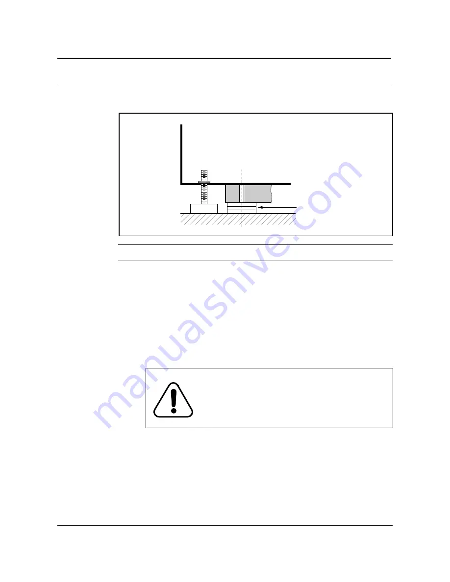
Cabinet installation (Zone 4 earthquake)
Figure 2-5
Levelling the cabinet
Step
Action
9
Tighten the anchor bolts using a socket wrench and extension handle. Torque
the bolts to 18 ft lbs.
10
Remove the flexible power cable from the enclosure. In addition, remove the
cable clamp from the interface plate.
Note:
Before removing the flexible power cable from the VCE power terminal
block (TB2), note the terminal where each wire is connected.
11
Connect a power cable between a suitable fused isolator on the customer
premises and the VCE power block through conduit or armoured cable.
Northern Telecom recommends the use of TECH 90 cable. The supply should
be from a 15 A breaker with an associated double-pole manual disconnect.
Note 1:
Ensure that the ac-power is disconnected from the 15 A breaker.
Note 2:
Be sure to connect the leads correctly to VCE power block TB2.
Connect the black (live) wire to L1; the white (neutral) wire to N; and the bare
or green (ground) wire to GRD. Ensure that the conduit or armoured cable is
properly secured to the side of the VCE.
Note 3:
A VCE must be grounded using the ground wire in the electrical
power cable (connect the cable ground wire to the cabinet GRD stud).
—continued—
DANGER
Danger of electrical shock
All electrical connections must be made by a
licensed electrician and follow all relevant local
electrical codes
.
VCE cabinet
Leveling
foot
Anchor
point
Shims
Floor


