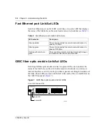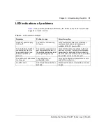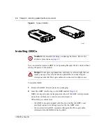
Chapter 3 Understanding the LEDs
29
Installing the Passport 1424T Series Layer 3 Switch
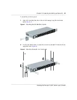
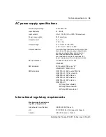
Figure 6 AC receptacle on the rear of the 1424T switch
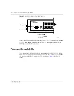
After you power the switch up, the LED indicators should respond as described in
.
Status LED
The
Status
LED lights when a remote management station initiates a console
management session over the switch’s RS-232 serial port.
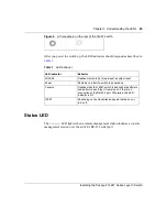
Table 1 LED behavior
LED indicator
Behavior
All LEDs
Flashes momentarily to represent a system reset.
Power
Remains on after the switch is powered up.
Console
Flashes while the 1424T switch loads onboard software
and performs a self-test. It remains on if there is a
connection at the RS-232 port. Otherwise, this LED
indicator is off.
100M
Depending on the transmission speed remains on or
turns off.
Summary of Contents for Passport 1424T
Page 8: ...8 316867 A Rev 00 ...
Page 12: ...12 Figures 316867 A Rev 00 ...
Page 14: ...14 Tables 316867 A Rev 00 ...
Page 20: ...20 Chapter 1 Introducing the 1424T switch 316867 A Rev 00 ...
Page 26: ...26 Chapter 2 Unpacking and setting up the switch 316867 A Rev 00 ...
Page 32: ...32 Chapter 3 Understanding the LEDs 316867 A Rev 00 ...


