Chapter 4 Installing gigabit interface converters
35
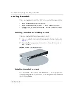
Installing the Passport 1424T Series Layer 3 Switch
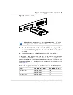
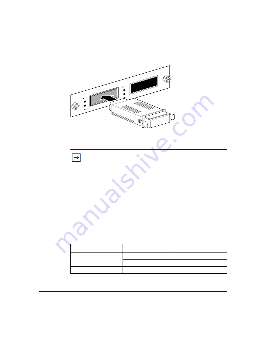
Figure 9 Installing a GBIC
3
When the electrical contacts in the rear of the GBIC are seated against the
contacts in the GBIC slot, gently press the module into the slot until you feel a
slight click.
4
Remove the rubber plug from the connectors to connect the cables.
When shorter lengths of single-mode fiber cable are used with the 1000BASE-ZX
and 1000BASE-XD GBICs, there is a risk of overloading the receiver. You may
need to insert an in-line optical attenuator at each end of the link between the fiber
optic cable plant and the receiving port on the 1000BASE-ZX or 1000BASE-XD
GBIC
Caution:
GBICs are keyed to prevent improper insertion. If the GBIC
resists pressure, do not force it. Remove it, turn it over, and reinsert it.
Table 4 In-line optical attenuators for 1000BASE-ZX and 1000BASE-XD GBICs
GBIC
Fiber optic cable span
In-line optical attenuator
1000BASE-ZX
Less than 25 km
10 dB
Less than 50 km
5 dB
1000BASE-XD
Less than 25 km
5 dB
2-Port GBIC Module
Tx
Rx
Act
Link
|
Act
Link
Tx
Rx
||
11061FA
Summary of Contents for Passport 1424T
Page 8: ...8 316867 A Rev 00 ...
Page 12: ...12 Figures 316867 A Rev 00 ...
Page 14: ...14 Tables 316867 A Rev 00 ...
Page 20: ...20 Chapter 1 Introducing the 1424T switch 316867 A Rev 00 ...
Page 26: ...26 Chapter 2 Unpacking and setting up the switch 316867 A Rev 00 ...
Page 32: ...32 Chapter 3 Understanding the LEDs 316867 A Rev 00 ...


