Chapter 4 Operating the Passport 8000 Series switch
79
Installing and Maintaining the Passport 8000 Series Chassis
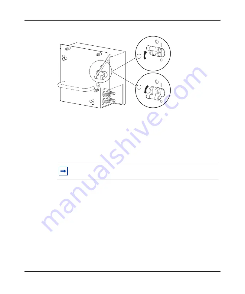
Figure 40
DC power supply power switch
3
Verify that the power output LED for each power supply lights green.
4
Verify that the power supply status LEDs and the fan LED on the 8691SF or
8692SF CPU modules light green.
5
Verify that air is flowing from the cooling fans out through the back of the
8010co chassis.
After you turn on the Passport 8000 Series switch, each module automatically
initiates a diagnostic test to verify proper module function (see
successful installation” on page 81
If the power supply LED remains off, or if you cannot feel air flow from the
8010co chassis vents, do the following:
1
Turn the power switch on each power supply to the off position.
2
If the installed chassis is the 8010co chassis and it is connected to the optional
breaker interface panel, make sure that the circuit breakers on the BIP are in
the off position.
3
Wait 1 minute.
Note:
The fan tray red fail LED may light briefly while the fans are
powering to operational speed.
10298FA
1 = On
2 = Off
2
1
-DC
+DC
Summary of Contents for Passport 8000 Series
Page 10: ......
Page 18: ...18 Tables 316314 E Rev 01...
Page 22: ...22 Preface 316314 E Rev 01...
Page 34: ...34 Chapter 1 Passport 8000 Series chassis hardware components 316314 E Rev 01...
Page 76: ...76 Chapter 3 Installing the 8010co chassis 316314 E Rev 01...
Page 118: ...118 Appendix A Technical specifications for the Passport 8000 Series Chassis 316314 E Rev 01...


