background image

3

OPERATION

Start Up

1) Add 87 octane (or higher)
unleaded gasoline to the engine
gas tank and SAE 10W-30 oil to
the engine oil tank. A different
viscosity oil may be required if
the compressor is operated at
different ambient temperatures.
Please refer to the engine
manual for more details.

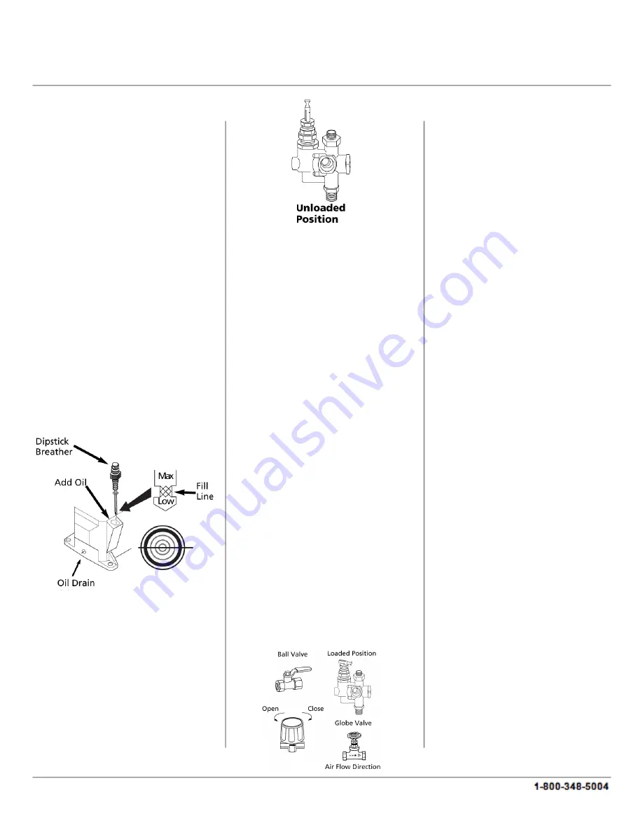
2) Remove the compressor
dipstick breather and fill the
pump to the proper oil level.
Use a single viscosity, ISO 100
(SAE 30) non-detergent
compressor oil. Do not use a
multi viscosity oil such as 10W-
30.

3) Turn the outlet valve or
regulator knob counterclockwise
to open the airflow.

4) Turn the manual unloader
lever to a vertical position in
order to allow the compressor
pump to run without
compressing air.

Starting A Gasoline Engine

1) Move the choke lever to the
CHOKE position and turn the
stop lever towards the ON
position.

2) Pull the start grip lightly until
resistance is felt, then pull on the
start grip briskly to start the
engine.

3) As the engine begins to warm
up, gradually move the choke
lever to the OPEN position.

4) Run the compressor at an
unloaded speed for
approximately 30 minutes in
order to break in the pump.

5) After approximately 30
minutes of run time, move the
unloader lever down to the
loaded position and turn the
regulator knob clockwise. The
compressor will begin to pump
air into the tank at this time.

When the maximum tank
pressure is achieved, the
compressor automatically
unloads, which brings the
engine to idle. The engine
remains at the idle state until the
pressure in the tank falls to a
preset level. The engine will then
accelerate and the compressor
will pump additional air into the
tank.

MAINTENANCE

WARNING: Release all
pressure from the system
before attempting to perform
any maintenance, relocate,
service or install the unit.

Check the air filter, oil level and
gasoline level before each use in
order to maintain efficient
operation of the unit.
The ASME safety valve should
be checked before each use. Pull
the ring on the safety valve and
allow the ring to snap back into
its normal position. This valve
automatically releases air if the
tank pressure exceeds a preset
maximum. If air leaks after the
ring has been released, or if the
valve is stuck and cannot be
actuated by the ring, the ASME
safety valve must be replaced.

Do not attempt to tamper with
the ASME safety valve.

With the engine OFF, clean any
debris from the engine, flywheel,
tank, air lines and pump cooling
fins.

Never attempt to repair or

feedback@natitools.com

Summary of Contents for 7295

Page 1: ...no liability for damage or accidents which arise due to non observance of these instructions and the safety information herein SPECIFICATIONS Engine 6 5 HP OHV Tank capacity 9 gallons Pressure 115 PSI Speed 1150 RPMs 12 CFM 90 PSI CAUTION FOR YOUR OWN SAFETY READ INSTRUCTION MANUAL COMPLETELY AND CAREFULLY BEFORE OPERATING THIS GAS COMPRESSOR Any failures made in following the safety regulations a...

Page 2: ...fore storing the unit 24 Do not spray flammable materials within the vicinity of an open flame or near ignition sources including the compressor unit 25 Do not smoke when spraying paint insecticides or other flammable substances 26 Use a facemask when spraying Spray in a well ventilated area to prevent health and fire hazards 27 Do not direct any sprayed materials at the compressor Keep the compre...

Page 3: ...pproximately 30 minutes of run time move the unloader lever down to the loaded position and turn the regulator knob clockwise The compressor will begin to pump air into the tank at this time When the maximum tank pressure is achieved the compressor automatically unloads which brings the engine to idle The engine remains at the idle state until the pressure in the tank falls to a preset level The e...

Page 4: ...properly aligned when this adjustment is made 4 To align the belt lay a straight edge against the face of the flywheel touching the rim at two places 5 Adjust the flywheel or motor pulley so that the belt runs parallel to the straight edge 6 Use a gear puller to move the pulley on the shaft and to tighten the fasteners 7 Adjust the brace and then tighten the fasteners braces and reinstall the belt...

Page 5: ... Clean or replace Defective safety relief valve Replace Pressure switch unloader leaks or does not work Realign stem or replace Leaking broken or worn inlet unloader parts at check valve Inspect parts and replace as requried Compressor viscosity is too high for the ambient temperature Drain the existing lubricant and refill the tank with the proper lubricant Belt tension is too tight or sheaves ar...

Page 6: ...e switch unloader leaks or does not work Realign stem or replace Leaking broken or worn inlet unloader parts at check valve Inspect parts and replace as requried Pressure switch unloader leaks or does not work Realign stem or replace Excessive condensation in receiver tank Drain receiver tank Light duty cycle Increase duty cycle Moisture in crankcase milky substance in oil Detergent lubricant in c...

Page 7: ...ck of maintenance This product is intended for personal use The warranty will be voided if used in commercial rental or industrial applications NATI shall in no event be liable for death injuries to persons or property or for incidental special or consequential damages arising from the use of our products To receive service under warranty the original manufacturer part must be returned for examina...

Page 8: ...8909528 12 13 9 GALLON 6 5HP TWIN TANK GAS AIR COMPRESSOR 8 Exploded View For customer service call 1 800 348 5004 or email feedback natitools com ...

Page 9: ...olt 4 1 Bolt 3 1 Cable 2 1 Engine 1 QTY Description No 40942 2 Drain Valve 28 42529 2 Quick Connect 29 2 Bolt 30 42531 1 Pressure Gauge 31 42532 1 Safety Valve 32 42533 1 Regulator 33 1 Grip 34 42534 1 Plastic Supply Line 35 1 Quick Connect Manifold 36 40933 1 Pressure Gauge 37 4 Washer 26 4 Bolt 27 38527 4 Bumper 25 42528 42527 SKU 4 Nut 23 4 Spring Washer 24 1 Tire 22 4 Axle 21 4 Cotter Pin 20 Q...

Page 10: ...Pump Assembly 10 For customer service call 1 800 348 5004 or email feedback natitools com ...

Page 11: ...alve Plate 11 Valve Seat 10 Aluminum Washer 9 Head Washer 8 Aluminum Pipe 7 Elbow 6 Exhaust Elbow 5 Filter 4 Head 3 Split Washer 2 Bolt 1 Description No 42554 42553 42552 SKU Bolt 47 M8 Nut 46 Split Washer 45 Bolt 44 Split Washer 43 Pulley 42 Bolt 41 Crankcase Back Cover 40 Crankcase Back Washer 39 O Ring 38 Bearing 37 Crank Shaft 36 Crankcase 35 Oil Drain Plug 34 O Ring 33 Oil Window 32 Bearing 3...

Reviews: