background image

Page 15 of 36 


Extension Cords 

WARNING


USE A PROPER EXTENSION CORD. Make sure your extension cord is in good condition. When 
using an extension cord, be sure to use one heavy enough to carry the current your product will draw. 
An undersized cord will cause a drop in line voltage, resulting in loss of power and cause 
overheating. 


Be sure your extension cord is properly wired and in good condition. Always replace a damaged 
extension cord or have it repaired by a qualified person before using it. Protect your extension cords 
from sharp objects, excessive heat and damp or wet areas.  

If an extension cord must be used, be sure it is: 


a 3-wire extension cord that has a 3-blade grounding plug, and a 3-slot receptacle that will accept the 
plug on the product, 


in good condition, 


plug is not worn, 


no longer than 50 feet (15.2 m), 


12 gauge (AWG) or larger. (Wire size increases as gauge number decreases. 10 AWG and 8 AWG 
may also be used. DO NOT USE 14 OR 16 AWG.) 

NOTICE: The use of an undersized extension cord will cause voltage to drop resulting in power loss to 
the motor and overheating. Instead of using an extension cord, increase the working reach of the air hose 
by attaching another length of hose to its end. Attach additional lengths of hose as needed. Always use a 
minimum 3/8” (9.5 mm) or greater air hose rated at 300 PSI. 


The smaller the wire’s gauge number, the greater the capacity of the cord. For example, a 14-gauge 
cord can carry a higher current than a 16-gauge cord. Minimum extension cord wire size is shown in 
the following table: 


Summary of Contents for NSLA1683066

Page 1: ...c Air Compressor Owner s Manual WARNING Read carefully and understand all ASSEMBLY AND OPERATION INSTRUCTIONS before operating Failure to follow the safety rules and other basic safety precautions may...

Page 2: ...that you read the entire manual to become familiar with this product before you begin using it This air compressor is designed for certain applications only Northern Tool and Equipment is not responsi...

Page 3: ...cting Hoses 13 Installation 13 Lubrication and Oil 13 Compatibility 13 Location 13 Humid Areas 13 Wiring 13 Wiring Instructions 14 Grounding 14 Grounding Instructions 14 Extension Cords 15 Voltage and...

Page 4: ...Motor Pulley Flywheel Alignment 24 Air Compressor Pump Intake and Exhaust Valves 24 Inspect Air Lines and Fittings for Leaks 25 Air Compressor Head Bolts Torqueing 25 Service and Adjustments 25 To Re...

Page 5: ...ner s Manual Compressor Insert Sheet Technical Specifications Property Specification Model NSLA1683066 Weight 165 lb 75 kg Height 48 Width 24 12 Running HP 1 6 Tank Capacity 30 Gallons Voltage Amps Ph...

Page 6: ...ned This product will be safer and do a better job at the capacity for which it was intended DO NOT use this equipment for a purpose for which it was not intended Industrial or commercial applications...

Page 7: ...flation Oil can leak or spill and could result in fire or breathing hazard serious injury or death can result Oil leaks will damage carpet paint or other surfaces in vehicles or trailers Always place...

Page 8: ...e product will operate properly and perform its intended function Replace damaged or worn parts immediately Never operate the product with a damaged part Do not use a product with a malfunctioning swi...

Page 9: ...ormed by authorized service center personnel in accordance with national and local electrical codes Failure to provide adequate grounding to this product could result in serious injury or death from e...

Page 10: ...tion to provide automatic power to the pressure switch and OFF O to remove power at the end of each use NOTE ALWAYS ensure the switch is in the OFF O position before removing or replacing the pressure...

Page 11: ...the regulator and is always less or equal to the air tank pressure 12 Universal Quick Connect Body The universal quick connect body accepts the three most popular styles of quick connect plugs Industr...

Page 12: ...ordered and that it has the required pressure rating for its intended use Attaching Vibration Pads Attach the two vibration pads to the bottom of the compressor feet as shown Installing Hoses WARNING...

Page 13: ...uld cause power loss to the motor THE AIR FILTERS MUST BE KEPT CLEAR OF OBSTRUCTIONS WHICH COULD REDUCE AIR FLOW TO THE AIR COMPRESSOR Humid Areas In frequently humid areas moisture may form in the pu...

Page 14: ...an CHECK with a qualified electrician or service person if you do not completely understand the grounding instructions or if you are not sure the tool is properly grounded Risk of electrical shock In...

Page 15: ...3 blade grounding plug and a 3 slot receptacle that will accept the plug on the product in good condition plug is not worn no longer than 50 feet 15 2 m 12 gauge AWG or larger Wire size increases as g...

Page 16: ...on a 15 amp circuit if the following conditions are met Voltage supply to circuit must comply with the National Electrical Code Circuit is not used to supply any other electrical needs Extension cord...

Page 17: ...motor nameplate and have the conversion completed by a licensed electrician Figure E How to Use Your Unit WARNING Do not operate this unit until you read this instruction manual for safety operation...

Page 18: ...a soap solution Correct if necessary NOTE Minor leaks can cause the air compressor to overwork resulting in premature breakdown or inadequate performance 8 Check for excessive vibration 9 After 30 mi...

Page 19: ...When using the regulator and other accessories refer to the manufacturer s instructions The compressor is ready for use After Each Use WARNING Risk of unsafe operation Firmly grasp air hose in hand w...

Page 20: ...ned water will corrode and weaken the air tank causing a risk of air tank rupture Drain tank to release air pressure before removing the oil fill cap or oil drain plug To ensure efficient operation an...

Page 21: ...f switch is in the OFF position 2 Allow the unit to cool 3 Remove the two outer metal covers A from the base C by pushing in on the cover and turning counter clockwise 4 Check the filter elements B If...

Page 22: ...l capacity is approximately 13 fluid ounces 113 6 ml Checking Oil 1 The oil level is in the middle of the sight glass position E in figure I 2 If needed remove the oil fill plug position D in figure I...

Page 23: ...ing Risk of unsafe operation Unit cycles automatically when power is on When performing maintenance you may be exposed to voltage sources compressed air or moving parts Personal injuries can occur Bef...

Page 24: ...to assure belt retention within the flywheel belt grooves To check alignment perform the following steps 1 Set the Auto Off lever to OFF unplug the unit and relieve all air pressure from the air tank...

Page 25: ...stable wrench loosen the outlet tube nut at air tank and pump Carefully move the outlet tube away from the check valve 4 Using an adjustable wrench loosen the pressure relief tube nut at the air tank...

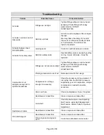
Page 26: ...to operate accessories Fittings are not secure and tight Tighten fittings where air can be heard escaping Check fittings with soapy water solution DO NOT OVERTIGHTEN Prolonged excessive use of air De...

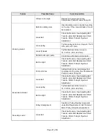
Page 27: ...t tension See Adjusting Belt Tension under Belt Replacement Belt Tension Motor Pulley Flywheel Adjustment Pump oil is low Add synthetic blend non detergent air compressor oil to pump See Compressor Pu...

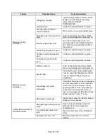
Page 28: ...rn Contact an authorized service center Water in pump oil Drain oil and refill pump with synthetic blend non detergent air compressor oil Moisture in pump crankcase Belt too tight Check belt tension S...

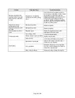
Page 29: ...knob has continuous air leak Damaged regulator Replace regulator Regulator will not shut off air outlet Damaged regulator Replace regulator Air tank pressure will not build Regulator open Rotate the...

Page 30: ...uantity 1 125 0175 Belt guard outer wire 1 2 061 0255 Screw 5M x 20mm 5 3 007 0010 V belt 4L 460 1 4 146 0016 Key 1 5 061 0238 Setscrew 5 16 18 2 6 006 0018 Pulley 1 7 059 0012 Bolt 5 16 x 1 2 4 9 125...

Page 31: ...3870 Label warning 1 31 065 0005 Nipple 1 4 x 2 1 2 1 32 026 0030 Cord power 1 33 034 0184 Switch pressure includes items 36 41 and 42 1 34 032 0025 Gauge 300 1 4 bottom connect 1 35 136 0077 Valve AS...

Page 32: ...042 0121 Head cylinder 2 6 046 0302 Gasket cylinder head 2 7 043 0207 Valve plate assembly includes items 6 and 8 2 8 046 0303 Gasket cylinder 2 9 019 0305 Filter assembly includes item 9A 2 9A 019 03...

Page 33: ...y not shown 1 36 165 0277 Overhaul kit includes items 6 8 9A 10 18 27 and 28 1 37 046 0307 Gaskets complete set includes items 6 8 18 27 and 28 1 38 S040 0469 Pump assembly includes items 1 40 1 39 06...

Page 34: ...failed due to lack of proper maintenance If a part is no longer available the part may be replaced with a similar part of equal function Any misuse abuse alteration or improper installation or operat...

Page 35: ...inadequate egress Damage caused by incorrect voltage improperly wired or failure to have a certified licensed electrician install the compressor will render this warranty null and void Damage caused...

Page 36: ...Page 36 of 36 Distributed by Northern Tool Equipment Company Inc Burnsville Minnesota 55306 www northerntool com Made in U S A of Domestic and Foreign Parts 200 3151 A_5 2 19...

Reviews: