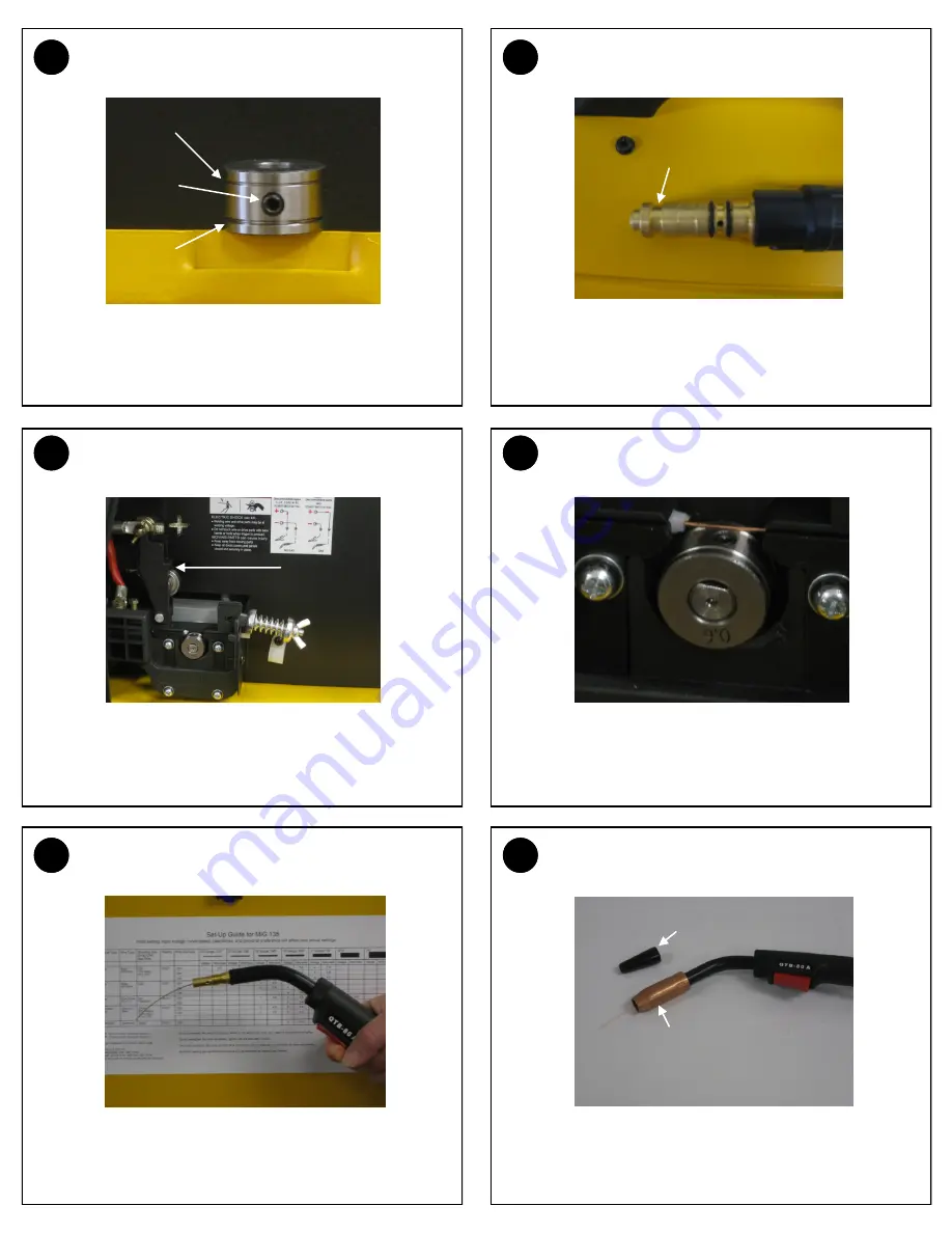
background image

3


DRIVE ROLL GROOVE SELECTION 

4


MIG GUN - MACHINE END 

7


FEED WIRE - OPEN TENSION ARM 

8


FEED WIRE - THREAD WIRE 

11


FEED WIRE - PULL TRIGGER TO FEED WIRE 

12


FEED WIRE - REINSTALL TIP AND NOZZLE 

The smaller groove on the drive roll is to be used with .023 wire. 
The larger groove can be used for .030 and .035 wire. Use the 
supplied “L” shaped hex wrench to loosen set screw and to align 
the proper groove to the wire path. Retighten set screw. 

This MIG gun is a one piece connection. Notice the retaining 
groove on the machine end. The hex-headed retaining screw in 
the step (6) will set down into this groove. 

Open the drive roll tension arm on the wire feeder. 

Feed the loose end of the wire through the Inlet Guide Tube, past 
the drive roll and into the back of the MIG Gun. Keep tension on 
the wire to prevent unspooling on the spool. Make certain wire is 
centered on groove and adjust drive roll (Step 3) if needed.  

Stretch out the MIG gun. Turn on input power and pull the trigger 
to feed the wire through the gun. Stop when the wire pushes 
through the end of the gun. 

Slide the correct size contact tip for the wire size you are using 
over the end of the wire and tighten clockwise to secure. Choose 
the correct nozzle, thread on nozzle and clip any excess wire. 

.023 

.030 
.035 

Set 

Screw 

Retaining 

Groove 

Flux-Cored Nozzle 

Hard Wire 

Nozzle 

Drive Roll 

Tension 

Arm 

Summary of Contents for MIG 135

Page 1: ... intended to provide quick instructions on the set up of your new welder Please take time to review the operator s manual prior to operating this unit MIG 135 Item 164611 For more help visit www ntwelderhelp com Or Call 1 877 304 0294 ...

Page 2: ...See Step 13 to adjust wire spool tension Remove Retaining Screw see step 6 Slide the machine end of the MIG gun into the front panel receptacle Push it all the way into the wire feeder as far as it will go Feed trigger leads through the opening in the front panel Tighten the retaining screw on the wire feeder housing to secure the gun Install trigger leads into the trigger lead receptacle Close th...

Page 3: ...down into this groove Open the drive roll tension arm on the wire feeder Feed the loose end of the wire through the Inlet Guide Tube past the drive roll and into the back of the MIG Gun Keep tension on the wire to prevent unspooling on the spool Make certain wire is centered on groove and adjust drive roll Step 3 if needed Stretch out the MIG gun Turn on input power and pull the trigger to feed th...

Page 4: ...nnects to the regulator The other end connects to the gas valve on the back of the machine Open the drive roll tension arm on the wire feeder Open the valve on the shielding gas bottle Turn on the unit power and pull the trigger Adjust the regulator to set for 20 cubic feet per min ute Reinstall the drive roll tension arm on the wire feeder On the wire compartment access panel is a set up guide Fi...

Reviews: