not attach the wires to the exhaust system, drive shaft, emergency brake cable, fuel line, or any
other components which may create damage to the wiring through heat or motion, or create a fire
hazard.
3.
If you drill through the bumper or any part of the body to route the wires, be sure to install a
rubber grommet in the hole to prevent fraying of the wires at that point.
4.
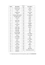
Route the POWER CABLE (#39) from the point the winch will be used to the battery. Following
the precautions discussed above.
5.
Remove the Red Clamp handle, and attach the red wire to the OVER-CURRENT PROTECTOR
(#31) which is mounted onto the Positive (+/ Red ) terminal of your battery.
6.
Remove the Black Clamp handle, and attach the black wire to the frame of your vehicle, creating
a secure electrical ground.
WARNING:
Always connect Red to Red (Positive to Positive) and Black to the vehicle’s frame, making a
ground connection, when using battery power from your vehicle.
Never continue use of your winch or other accessory until the battery is completely run down.
This can permanently damage your battery!
You may wish to keep your engine running while using this winch, to continually recharge the
battery. However, exercise extreme caution when working around a running vehicle. (See USING
YOUR WINCH on page 7 of this manual.)
Do not use a dirty, corroded or leaking battery. You may suffer injury from acid burns.
Always wear ANSI-approved safety glasses when working around or with a battery.
OPERATION
MOUNTING YOUR WINCH
Your winch is designed to be mounted temporarily, using the Trailer Hitch Mounting Bracket.
However, you may also mount your winch permanently.
Permanent Mounting
1. Select a mounting site on the bumper of your vehicle, truck bed, boat trailer, or other suitable
location.
NOTE:
This winch can generate 2000 lbs. pulling force. Be sure the location you select
can withstand this much force. You may need to use steel reinforcement plates, or weld on
additional bracing, depending on the desired mounting location.
2. Align the winch with the desired location, and mark for drilling the locations of the 4 holes on the
base of the winch.
3. Drill these locations on your vehicle.
4. Using hardened steel bolts at least 3/8in. in diameter, install your winch to the location.
Temporary Mounting
1. Attach the three Plate Stud Bolts to the Adapter Plate, as shown, (see Diagram on page 9)
using
the supplied Nuts. Tighten securely.
2. Index the heads of the Plate Studs into the keyhole slots on the back of the winch.
Summary of Contents for 141220
Page 9: ...DIAGRAM PARTS LIST...


