background image

K

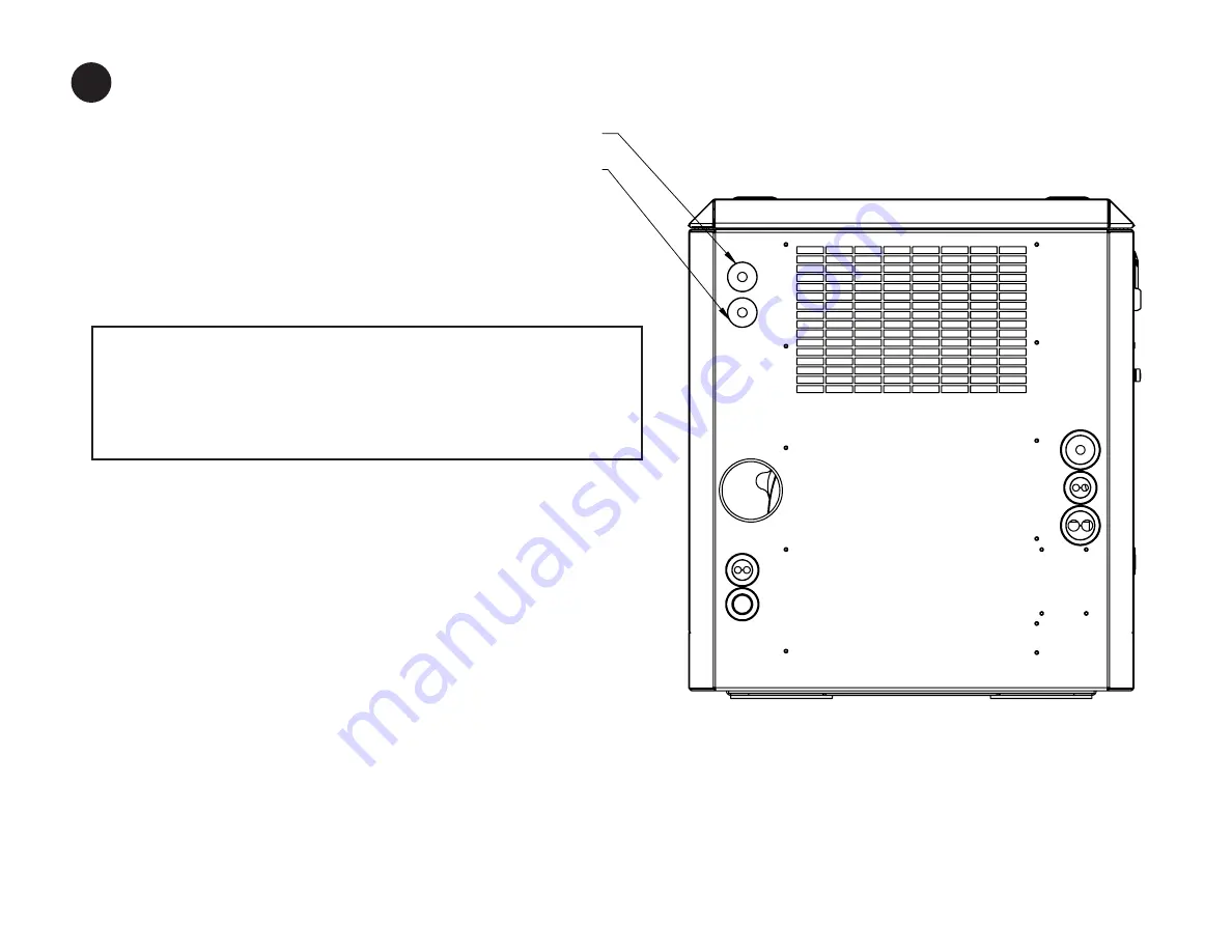
REAR PANEL VIEW

FROM SEA WATER PUMP OUTLET TO SIPHON BREAK

FROM SIPHON BREAK TO HEAT EXCHANGER INLET

06-78700 M864W3  GEM Page 13

13.

IF YOU HAVE CHOSEN TO INSTALL A SIPHON BREAK:
Note the two plugged penetrations in the top left corner

of the rear panel.  These are the ports through which the 

siphon break lines will be routed. 

At this time you should refer to the plumbing diagram in the

mounting and exhaust sections of the IM1000 Installation manual. 
Remove the white plastic hole plugs by pushing them out 

from the inside and replace with the two rubber grommets

(ITEM#14) provided. 
CAUTION. GENERATOR SETS WITH WET EXHAUST THAT ARE 

INSTALLED NEAR OR BELOW THE VESSEL'S HULL WATER LINE 

MUST USE A SIPHON BREAK TO PREVENT BACK FLOW OF 

WATER INTO THE ENGINE. THIS BACKFLOW CAN RUIN AN

ENGINE AN POSSIBLY SINK THE VESSEL.

Disconnect the hose from the sea water pump output and

a.

the inlet to the heat exchanger. Replace this single hose

with two 3/4" ID lines, one from the sea water output and

the other to the heat exchanger inlet.  These hoses must

be of adequate length to mount a siphon break a min

of 12 inches above the vessel's loaded water line.

b.     Pass these lines through the two holes in the rear panel, 

as indicated per the diagram. 

c.     For more information, see the "Exhaust" section of the 

IM 1000 Installation Manual. 


OUT TO VENTED LOOP

IN FROM VENTED LOOP

FOR APPLICATIONS USING A SIPHON BREAK:

Remove the white plastic hole plugs by pushing them out from the inside and 
replace with the two rubber grommets (item 15) provided. 

a. Disconnect the hose from the seawater pump output and from the rubber  
  elbow on the expansion tank. Install two lengths of 3/4” hose. The hoses  
  must be of adequate length to allow mounting of a siphon break, a minimum  

  of 12 inches above the vessel’s loaded water line.

b. Pass the seawater pump output hose through the top hole in the panel. The  
  hose from the expansion tank must go through the bottom hole in the panel.
c. For more information, see the “Exhaust” section of IM1000 Installation   
 Manual. 

CAUTION: GENERATOR SETS WITH WET EXHAUST THAT ARE 

INSTALLED NEAR OR BELOW THE VESSEL’S WATER LINE MUST USE 

A SIPHON BREAK TO PREVENT BACKFLOW OR WATER INTO THE 
ENGINE. THIS BACKFLOW CAN RUIN AN ENGINE AND POSSIBLY 
SINK THE VESSEL.

14

Summary of Contents for GEM M864W3

Page 1: ...www northern lights com M864W3 GEM Series Sound Enclosure Assembly Instructions 06 78700 M864W3 GEM COVER PAGE...

Page 2: ...el 907 562 2222 Fax 907 563 1921 East Coast Branch 15 Aegean Dr Suite 4 Methuen MA 01844 Tel 978 475 7400 Fax 978 475 7745 Gulf Branch 19 Veterans Memorial Blvd Kenner LA 70062 Tel 504 360 2180 Toll F...

Page 3: ...hex head capscrew 12 00776 4 loose bagged 5 Service side bottom valence assembly 06 78707 1 6 Non service side bottom valence assembly 06 78709 1 7 Front bottom valence assembly 06 78719 1 8 Non serv...

Page 4: ...ewed from the rear the right hand side is the service side and should be exposed for easy maintenance access Install the generator set in the vessel as near to a level attitude as possible Ensure that...

Page 5: ...STEP 2 WHEN THE REAR PANEL ASSEMBLY IS SECURED INSERT GENSET AIR INTAKE SNORKEL HOSE INTO THE RECIEVER AS SHOWN PUSH INTO HOLE FIRMLY BUT DO NOT FORCE HOSE ALL THE WAY IN THERE IS A TAB STOP THAT LIMI...

Page 6: ...PANEL PUSH FIRMLY TO SNAP INTO PLACE DISPLACED PINS MAY BE RE SEATED USING A LONG TOOL SUCH AS A SCREW DRIVER OR PRY BAR FROM THE INSIDE MOVE SOUND FOAM OUT OF THE WAY FOR ACCESS TO PINS D STEP 5 INS...

Page 7: ...located at the fuel manifold on the base frame of the generator set s right hand side through the bottom hole in the right side of the rear panel d Connect the DC control panel harness to the genset...

Page 8: ...SCREW B THUMB SCREW B DETAIL F THUMB SCREW B DETAIL G THUMB SCREW A 5 PANEL ATTACHES TO REAR PANEL AND LOWER VALENCE WITH THUMB SCREWS A AND B WITH PANEL IN PLACE USE THUMB SCREW A TO RETAIN SIDE PANE...

Page 9: ...9 INSTALL FRONT PANEL ASSEMBLY ITEM 10 POSITION FRONT PANEL ON TOP OF THE FRONT LOWER VALENCE NOTE THE PINS IN THE BOTTOM OF THE FRONT PANEL ALIGN TO HOLES IN THE LOWER VALENCE ENGAGE AND SECURE TO TH...

Page 10: ...SOUND FOAM OMITTED FOR VIEW CLARITY NOTE POSITIVE TERMINAL POLARITY POSITION AT TOP 06 78700 M864W3 GEM Page 7 F STEP 10 PRIOR TO INSTALLING THE SERVICE SIDE AFT PANEL ITEM 9 THE LEAK ALARM LIGHT AND...

Page 11: ...ITH THE END PLUG REMOVED B ENGINE WIRE HARNESS CONNECTOR END PLUG SHIPPED LOOSE SOUND SHIELD WIRE HARNESS E STOP SWITCH LEAK ALARM LIGHT FLOAT SWITCH TO BE CONNECTED TO ENGINE WIRE HARNESS C STEP 13 A...

Page 12: ...AIL M THUMB SCREW A 06 78700 M864W3 GEM Page 9 G STEP 11 INSTALL SEAL BAR ASSEMBLY ITEM 11 LOCATE BAR TO CORRESPONDING HOLES AND SECURE WITH THUMB SCREW A FOUR PLACES HAND TIGHTEN FIRM DO NOT USE TOOL...

Page 13: ...2 NOTE THAT THE PANEL HAS LOCATING PINS UNDER THE MATING FLANGE 6 TOTAL ALIGN THESE WITH THE CORRESPONDING HOLES ON THE TOP OF THE FRONT AND REAR PANELS ASSEMBLIES REFER TO DETAILS N AND O THE RING LA...

Page 14: ...ATOR PINS ITEM 13 GUIDE THE BLACK NYLON LOCATOR PINS ON PANEL ITEM 13 INTO THE CORRESPONDING SLOTS ON THE LOWER VALENCE TWIST RING LATCH TO CLOSE AND LOCK THE RING LATCH IS PRESET FROM THE FACTORY BUT...

Page 15: ...PAWL POINTING TOWARDS SLOT LOOSEN THE BOTTOM NUT TURN TOP NUT TO CHANGE POSITION OF PAWL AND THEN RE TIGHTEN THE BOTTOM NUT ENSURE THE NUT IS FULLY TIGHT BEFORE OPERATING THE LATCH 4 AN IDEAL LATCH C...

Page 16: ...t These hoses must be of adequate length to mount a siphon break a min of 12 inches above the vessel s loaded water line b Pass these lines through the two holes in the rear panel as indicated per the...

Page 17: ......

Page 18: ...3 QTY 1 ITEM 11 TOP PANEL ASSEMBLY 06 78705 QTY 1 ITEM 12 SERVICE SIDE FWD PANEL ASSEMBLY 06 78711 QTY 1 ITEM 13 06 78700 M864W3 GEM Page14 PACKING LIST CABLE ROUTING CLIP 00 40052 QTY 2 E STOP LEAK A...

Reviews: