background image

OM844W3  11/13

24

Servicing

2. Here are acceptable water quality specifications:

3.  If chlorides, sulfates or total dissolved solids are 

higher than the above given specification, the water 

must be distilled, demineralized, or 

  deionized before it is used in a cooling system.

4.  If total hardness is higher than 170 ppm and all other 

parameters are within the given 

  specifications, the water must be softened before it is 

used to make coolant solution.

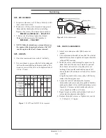
SP13.  CHECK THE COOLANT LEVEL

1.  Check the coolant level each day before starting the 

engine. Check the water level by removing the 

  pressure cap from the expansion tank. 

  In order to give the cooling water an opportunity to 

expand, the level should be about 1 in. (2.5 cm) below 

the filler cap sealing surface when the engine is cold.

2.  The pressure valve in the filler cap releases when the 

pressure is approximately 7 PSI (0.5 bar). Use a cap 

pressure tester to check cap if you suspect it is faulty.

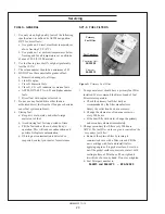
SP14.  COOLING SYSTEM FLUSHING

1.  Flush the cooling system every 2500 hours. 

2.  Marine sets:

  a.  Remove expansion tank cap and drain engine 

   block.

  b.  Open block drain cock. Remove hose from 

    bottom of heat exchanger tank.

  c.  Pour clean water into expansion tank until water 

    coming from drains is free of discoloration and 

    sediment. Let water drain completely. Close 

    drains and refill with recommended mixture.

3.  Coolant Specifications:

  Use 50% distilled water / 50% ethylene glycol 

  antifreeze mix. Antifreeze mixture is recommended

  as a good year-round coolant.

4.  Check hoses and connections and repair any leak-

age.

SP15.  HEAT EXCHANGER 

1.  Clean the heat exchanger core after 2500 hours of 

operation.

2.  Drain expansion tank and heat exchanger.

3.  Remove heat exchanger end covers and remove 

core.

4.  Clean the inside of exchanger core tubes using 

  a metal rod. Flush, inspect and clean again if 

 necessary.

5.  Reassemble. Fill the cooling system, start the engine 

and check for leaks.

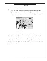
SP17.  RAW WATER PUMP 

1.  Change the seawater pump impeller every 1000 

hours, or as needed.

2.  Remove the pump end cover.  Pry out the impeller 

using needle-nose pliers or two screwdrivers. 

  Be sure you remove all pieces of failed impeller.

  NOTE:  Place some kind of protection under the 

screwdrivers in order not to damage the pump 

housing. If the impeller has broken into pieces, 

remove front heat exchanger end cover and inspect 

for impeller pieces. Clean inlet to heat exchanger 

bundle and reassemble.

3.  Clean the inside of the housing.

4.  Press in the new impeller and place the sealing 

washers in the outer end of the impeller center if this 

has not already been done.

5.  Replace the cover using a new gasket.


NOTE:  Make sure that there is always an extra 

impeller and cover gasket in reserve on board.

GENERATOR ENDS

  The maintenance and operation recommendations 

for the generator end are in a separate Owner’s 

Manual. If you do not have one of these manuals, 

contact your local Northern Lights dealer.

ELECTRICAL SYSTEM - GENERAL

1.  Never switch battery switch off or break the circuit 

between the alternator and batteries while the engine 

is running. Regulator damage can result.


Parts Grains

Contaminates 

per Million  per Gallon

Maximum Chlorides 

40 

2.5

Maximum Sulfates 

100 

5.9

Maximum Dissolved Solids 

340 

20.0

Maximum Total Hardness 

170 

10.0

PH Level 5.5 to 9.0

revised 11-8-13

Summary of Contents for M20CRW3

Page 1: ...OM844W3 For Models M844W3 M844DW3 M844LW3 and M20CRW3 OPERATOR S MANUAL Marine Generators Marine Diesel Engines Land Based Generators ...

Page 2: ... other reproductive harm CALIFORNIA Proposition 65 Warning Northern Lights 4420 14th Avenue N W Seattle WA 98107 Tel 206 789 3880 Fax 206 782 5455 Copyright 2013 Northern Lights Inc All rights reserved Northern Lights and the Northern Lights logo are trademarks of Northern Lights Inc Printed in U S A PART NO OM844W3 11 13 ...

Page 3: ...3 Marine Generator older baseframe 10 M844W3 Marine Generator new baseframe 11 M20CRW3 Commercial Generator 12 CONTROL PANELS 13 OPERATING PROCEDURES Break in Period 14 Before Starting 14 Starting 14 Operating 14 Stopping 14 Shutdowns and Alarms 15 Spare Parts 15 SERVICING SCHEDULE CHART 16 SERVICING Lubrication General 18 Checking Oil 18 Oil Changes 18 SERVICING continued Changing Oil Filter 18 A...

Page 4: ...The long stroke engine is designated 844LW3 You will need to know which engine you have to use this manual and to order parts W New winding D Series Designation L Long stroke version C Commercial version 3 Tier 3 Northern Lights marine diesel generator set with an 844 engine and a PX 316K2 generator end M 844 M844W3 Your set has three serial numbers 1 an engine number stamped on the block 2 a gene...

Page 5: ...gns in good and clean condition Replace missing or damaged signs Be sure new equipment components and repair parts include the current safety signs For replacement signs proper placement of safety signs or clarification on any safety issue consult your Northern Lights dealer or the factory There can be additional safety information contained on parts and components from outside suppliers that is n...

Page 6: ...moving parts have stopped before making any adjustments connections or performing any other type of service to the engine or other driven equipment Prevent accidental discharge of starting fluids by storing all cans in a cool safe place away from sparks or open flame Store with cap securely on container Never incinerate or puncture a fuel container Prevent fires by keeping machine clean of accumul...

Page 7: ...trolyte is poisonous and strong enough to burn skin eat holes into clothing and other materials and cause blindness if splashed into eyes To Avoid Hazards Fill batteries only in well ventilated areas Wear appropriate eye protection and rubber gloves Never use air pressure to clean batteries Wear appropriate ventilation equipment to avoid inhaling fumes when adding electrolyte Do not spill or drip ...

Page 8: ...d Dispose of paint and solvent properly Service Cooling System Safely WARNING Opening a pressurized cooling system can release explosive fluids and causing serious burns Before opening any pressurized cooling system make sure the engine has been shut off Do not remove a filler cap unless it is cool enough to comfortably grip with bare hands Slowly loosen cap to relieve pressure before opening full...

Page 9: ... water source components between the high pressure fuel pump and nozzles on engines with high pressure fuel systems ONLY AUTHORIZED TECHNICIANS CAN PERFORM REPAIRS ON AN HIGH PRESSURE FUEL INJECTION SYSTEMS Avoid Hot Exhaust WARNING Avoid exposure to and physical contact with hot exhaust gases Exhaust parts and streams can reach high temperatures during operation leading to burns or other serious ...

Page 10: ...t be achieved at the local supply valve shut off valves further back in the system and re check the bleed off point until complete shut off is achieved Affix a DO NOT OPERATE tag to each valve handle that requires shut off Each DO NOT OPERATE tag must be signed and dated by the authorized technician servicing the equipment Lock Out Tag Out Instructions Air Hose Connected Pneumatic Equipment Equipm...

Page 11: ...OM844W3 11 13 9 Notes ...

Page 12: ...ug in 23 AC Circuit Breaker for Automatic Voltage Regulator 24 Expansion Tank Exhaust Manifold Heat Exch Tank Service Side 5 Non Service Side 5 Figure 1A and 1B M844W3 25 Coolant Drain 26 Wet Exhaust Elbow 27 Junction Box 28 Starter 29 Alternator 30 Belt Guard 31 Coolant Thermostat behind 32 Water Temperature Sender 10 Oil Fill Side 11 Raw Water Pump 12 Raw Water Inlet 13 Vibration Mount 14 Oil Pr...

Page 13: ...r for Automatic Voltage Regulator 24 Expansion Tank Exhaust Manifold Heat Exch Tank Service Side 5 Non Service Side 5 Figure 1A and 1B M844W3 2 1 22 4 5 8 9 7 6 3 11 12 13 14 10 15 18 16 17 19 20 21 22 25 Coolant Drain 26 Wet Exhaust Elbow 27 Junction Box 28 Starter 29 Alternator 30 Belt Guard 31 Coolant Thermostat behind 32 Water Temperature Sender 7 11 31 32 24 27 28 13 29 30 26 25 9 Injection P...

Page 14: ... 20 AC Circuit Breaker for Automatic Voltage Regulator 21 Expansion Tank Exhaust Manifold Heat Exch Tank 22 Coolant Drain 23 Wet Exhaust Elbow Figure 2A and 2B M20CRW3 24 Junction Box 25 Starter 26 Alternator 27 Belt Guard 28 Coolant Thermostat behind 29 Water Temperature Sender 10 Raw Water Pump 11 Raw Water Inlet 12 Vibration Mount 13 Oil Pressure Sender 14 Freshwater Block Drain 15 Oil Dipstick...

Page 15: ... it will return to RUN position To stop the engine hold the switch in the STOP position until the engine has completely stopped NOTE The rocker switch is used on Series 1 panels only and has a light that glows when the set is running 3 HOUR METER Keeps track of engine running time 4 OIL PRESSURE GAUGE Shows the oil pressure in the engine lubricating system 5 ENGINE TEMPERATURE GAUGE Registers the ...

Page 16: ...o 20 seconds before starting a cold engine Holding the switch too long can burn out the glow plugs This step is not necessary if the engine is already warm 2 While holding the Shutdown Bypass Preheat switch in the ON position push the Engine Control switch to the START position 3 As soon as the engine starts release both switches Do not crank the starter for more than 10 seconds consecutively If t...

Page 17: ...ure within normal temperature range a Thisshutdowncouldhavehappenedbecauseofa too high exhaust temperature This could have been caused by a damaged impeller or a partially blocked sea water strainer Check the sea water strainer first If it is clear then check the condition of the sea water pump impeller b Check the engine crankcase oil level c If the oil level is low fill with recommended lubricat...

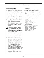
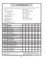
Page 18: ...e on chart 3 Whenever necessary 4 More often if necessary 5 After first 50 hours then at 100 hours then at every 200 hours Servicing Schedule Chart SERVICE 50 250 500 1000 2500 POINT PAGE OPERATION DAILY Hours Hours Hours Hours Hours ENGINE SP1 12 Check oil level SP2 12 Change engine oil 1 5 SP3 12 Change lube oil filters 1 5 SP4 13 Check air cleaner 1 4 SP5 13 Check V belt tension SP6 13 Check va...

Page 19: ...OM844W3 11 13 17 Service Record Notes ...

Page 20: ...nge oil every 100 hours or six weeks whichever comes first 4 Change oil at the end of each season and the beginning of each season 5 Change oil when engine is warm 6 Dispose of waste oil in an approved manner 7 Never use a flushing oil 8 Loosen the clamp on the oil change tube Remove cap Drain oil Replace the cap and tube 9 Refill engine with recommended oil for the season 10 Engine capacity with ...

Page 21: ...justments should be done after the cylinder head bolts have been re tightened Engine should be cold and NOT running 3 Watch the valves while turning the engine over by hand Turn until the inlet valve starts to open and the exhaust valve starts to close the valves are rocking Then turn the crankshaft one more full turn and adjust the clearance on both valves for this cylinder Align the top mark of ...

Page 22: ...end of each day s operation This will reduce condensation and possible biological contamination d If biological contamination is detected or suspected contact your dealer for assistance SP7 9 FUEL FILTERS Figure 9 Primary Fuel Filter 1 Your generator set should have a primary fuel filter installed We recommend the Racor brand of fuel filter water separators a Check the primary fuel filter daily as...

Page 23: ...em 1 The fuel system is self bleeding However any system may need manual bleeding when a A new fuel filter is installed b The engine has run out of fuel c The fuel lines injection pump or any other fuel system component has been removed and installed 2 Loosen bleed bolt A Figure 10 on top of the filter Pump hand primer B on fuel lift pump until pure fuel no bubbles escapes from bleed bolt A Tighte...

Page 24: ...ver lines inlets and injection pump outlets Figure 15 Remove return line Figure 16 Unscrew injector Figure 17 Remove and replace copper sealing washer Figure 18 Reinstall injector Torque to proper tightness Servicing Figure 14 Remove return line nuts For illustration purposes only your model is different ...

Page 25: ... bolts to 22 30 ft lbs d Install delivery lines Leave loose at injectors for bleeding e Crank engine to fill lines Tighten lines at injectors to 11 18 ft lbs Start engine and check for leaks using a piece of paper or cardboard DO NOT use hand to check for leaks SP12 INJECTION PUMP 1 Since operating conditions may vary considerably it is difficult to give a definite interval for checking the inject...

Page 26: ...ak age SP15 HEAT EXCHANGER 1 Clean the heat exchanger core after 2500 hours of operation 2 Drain expansion tank and heat exchanger 3 Remove heat exchanger end covers and remove core 4 Clean the inside of exchanger core tubes using a metal rod Flush inspect and clean again if necessary 5 Reassemble Fill the cooling system start the engine and check for leaks SP17 RAW WATER PUMP 1 Change the seawate...

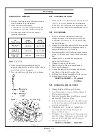
Page 27: ...ster battery to positive terminal of main battery Then connect negative terminal of booster battery to ground on the engine block see Figure 20 4 Remove booster battery after starting engine 5 Sealed batteries See manufacturer charging and booster instructions SP 18 19 BATTERY CARE 1 Check electrolyte level every 50 hours or once per month Add distilled water to manufacturer s recommended level 2 ...

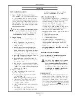
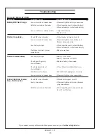
Page 28: ... plug connection Low battery output Check specific gravity of each battery Check electrolyte level of each battery Defective electrical system Repair or replace ground wire Starter Cranks Slowly Low battery output Battery is too small Battery cables are too small Check specific gravity Replace battery if necessary of each battery Check electrolyte level If low fill cells with distilled water of ea...

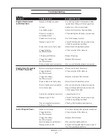
Page 29: ... Runs Irregularly Below normal engine temperature Remove and check thermostat or Stalls Frequently Clogged primary Clean or replace filter element fuel filter element Clogged secondary Replace secondary filter element fuel filter element Water or dirt in the fuel system Drain flush fill and bleed system Dirty or faulty injection nozzles Have your dealer check injection nozzles Air in fuel system I...

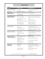
Page 30: ...ystem Defective thermostat Remove and check thermostat Defective temperature gauge Check water temperature with thermometer and replace gauge if necessary Water pump impeller worn broken Check impeller and replace if necessary V belts slipping Fix belts to proper tension Engine Knocks Insufficient oil Call your dealer Injection pump out of time Call your dealer Below normal engine temperature Chec...

Page 31: ...proper level Improper type of oil Drain and fill crankcase with correct oil Partially plugged oil filter Replace filter Check bearings oil pump and relief valve for wear High Oil Consumption Break in period Oil consumption decreases after break in Crankcase oil too light Use proper viscosity oil Oil leaks Check for leaks in lines around gaskets and drain plug Engine Emits Black Clogged or dirty ai...

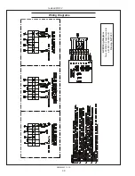
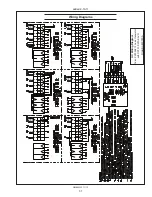
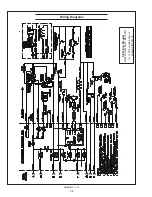
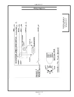
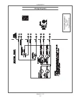
Page 32: ...OM844W3 11 13 30 Wiring Diagrams AC Wiring Diagram Taiyo PX300K2 4 Lead Generator with DST 102FAK AVR Drawing B 9724C revised 8 6 12 ...

Page 33: ...OM844W3 11 13 31 Wiring Diagrams AC Wiring Diagram Taiyo PX300K2 12 Lead Generator with DST 100 2FAK AVR Drawing B 9723A added 9 19 11 ...

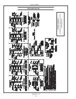
Page 34: ...OM844W3 11 13 32 Wiring Diagrams AC Wiring Diagram AVR SX460 with Stamford 4 and 12 Wire Drawing B 5703L Revised 6 8 12 ...

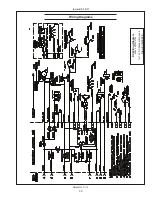
Page 35: ...OM844W3 11 13 33 Wiring Diagrams DC Wiring Diagram M844 M20CRW for 12 VDC Standard Ground Drawing B 9902B revised 9 19 11 ...

Page 36: ...OM844W3 11 13 34 Wiring Diagrams DC Wiring Diagram M844W3 M844LW3 M20CRW3 for 12 VDC Isolated Ground Drawing B 10111A ...

Page 37: ...OM844W3 11 13 35 Wiring Diagrams DC Wiring Diagram Control Panel S 1B Drawing A 3170 added 9 19 11 ...

Page 38: ...OM844W3 11 13 36 Wiring Diagrams Panel Wiring Diagram S 3C Oceanline Viewline Panels 12V Drawing A 12572B added 9 19 11 ...

Page 39: ...OM844W3 11 13 37 Wiring Diagrams Panel Wiring Diagram S 3C Viewline Panels 12V Drawing A 12645A added 6 8 12 ...

Page 40: ...OM844W3 11 13 38 Wiring Diagrams DC Wiring Diagram M844W M20CRW for 24 VDC Standard Ground Drawing B 9907C Revised 6 8 12 ...

Page 41: ...OM844W3 11 13 39 Wiring Diagrams DC Wiring Diagram M844W M20CRW for 24 VDC Isolated Ground S 1B Drawing B 9906B revised 6 8 12 ...

Page 42: ...OM844W3 11 13 40 Wiring Diagrams DC Wiring Diagram Control Panel for 24 VDC Isolated Ground Drawing A 4792 added 9 19 11 ...

Page 43: ...OM844W3 11 13 41 Wiring Diagrams Panel Wiring Diagram S 3C Oceanline Viewline Panels 24V Drawing A 12594B added 9 19 11 ...

Page 44: ......
Page 45: ...4420 14th Ave NW Seattle WA 98107 Tel 206 789 3880 1 800 762 0165 www northern lights com Northern Lights and Lugger are registered trademarks of Northern Lights Inc 2013 All rights reserved Litho USA ...

Reviews: