background image


3


P0908433 01

Flash Installation Guide


Environment check list


The installation area should be:


clean, free of dust, dry and well ventilated


between 0˚ and 40˚ Celsius


non-condensing relative humidity between 5% and 95%


at least 4 m (about 13 ft) from any equipment that could produce 
electromagnetic, radio frequency and electrostatic interferences


a wall area approximately 1 m square (about 3 ft sq)


within 305 m (1000 ft) of the Norstar KSU


within 1.5 m (about 5 ft) of a three-wire grounded electrical outlet


a minimum of 16 cm (about 6 in) from a corner wall or other 
component


a minimum of 46 cm (about 18 in) from the floor


Note


: The distance from the floor should be enough to prevent water 

damage. 


Electrical check list


The electrical requirements for the Flash module are:


115 VAC nominal (105 to 129 volts)


frequency 60 Hz nominal (47 to 63 Hz)


current 0.2 Amps maximum 


3rd wire ground


unswitched


DO NOT


 connect the module to a socket on a circuit that is likely to be 

overloaded or used by large office equipment or power tools.


Installation check list


Installing a Flash module means you must:


Install the module
• mount the unit to the wall
• install the Feature Cartridge
• connect the station port(s)
• connect the power supply


Determine the Feature Codes


Initialize Flash Voice Mail Light, Flash Voice Mail, Flash ACD or both 
Flash Voice Mail and Flash ACD


Name the Flash port

Summary of Contents for Flash Basic 2

Page 1: ...P0908433 01 Printed in Canada Norstar and Flash are trademarks of Northern Telecom Copyright Northern Telecom 1999 Flash Installation Guide...

Page 2: ......
Page 3: ...e Feature Cartridge 7 Connecting the power supply 8 Initializing Flash 9 Preparing Flash 9 Determining the KSU software version 10 Selecting the Feature Code range 12 Initializing Flash Voice Mail Lig...

Page 4: ...ii Flash Installation Guide P0908433 01 Reinstalling Flash 23 Appendix A Upgrading to Flash 25 Index 27...

Page 5: ...interference to radio communications It has been tested and found to comply with the limits for a Class A computing device pursuant to Part 15 of the FCC Rules and CSA specification C108 8 which are...

Page 6: ...rthern Telecom Inc Product Service Center 640 Massman Drive Nashville TN 37210 Tel 1 800 466 7835 Note You receive a Repair Authorization number RA when you call the repair center in Nashville This nu...

Page 7: ...ou must use a four channel expanded Flash system to run both Flash Voice Mail and Flash ACD Flash ACD is not available if you have a Flash Voice Mail Light system For more information about Flash hard...

Page 8: ...age check list Make sure the package contains a Flash module a power supply a teladapt cord two cords are required for a Model 4 shrink wrapped packages of documentation a Feature Cartridge Special pa...

Page 9: ...46 cm about 18 in from the floor Note The distance from the floor should be enough to prevent water damage Electrical check list The electrical requirements for the Flash module are 115 VAC nominal 1...

Page 10: ...e to the KSU in a place free of traffic The area should also be free of dampness and dust IMPORTANT If you are replacing a StarTalk Mini with a Flash read Appendix A before proceeding with the install...

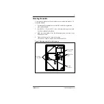
Page 11: ...backboard 2 Install a 10 X 2 5 cm 10 X 1 in wood screw in the top screw hole but do not tighten it completely 3 Make sure the module is level Install and tighten a wood screw in the bottom screw hole...

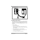
Page 12: ...tallation Guide that came with the Norstar KSU To connect the module 1 Locate the distribution block 2 Ensure there are available station ports at the distribution block You need one station port for...

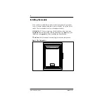
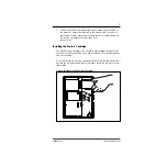
Page 13: ...not use a teladapt cord longer than 4 5 m about 14 ft Installing the Feature Cartridge The Flash Feature Cartridge is a PCMCIA ROM card that contains all the Flash Voice Mail Light Flash Voice Mail o...

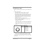
Page 14: ...d Refer to Table 1 3 Plug the power supply into a grounded power outlet The red power Light Emitting Diode LED on the module should light up If the LED does not light up Verify there is AC power If th...

Page 15: ...ding digit for Group Lists if the Group List option is enabled Initializing Flash ACD establishes the primary and alternate languages of the Flash voice prompts This guide shows the steps to initializ...

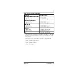
Page 16: ...te the software version For example if the display shows SP 30MUJ24 DR5 the version is DR5 9 24 Norstar uses letters of the alphabet to designate version numbers The letter A represents 0 the letter B...

Page 17: ...software Flash Voice Mail software Flash ACD software KSU Version SP Software Number Compact Disconnect Supervision English French English Spanish SP 30NSE05 DR5 or greater SP 30NYE05 DR5 or greater...

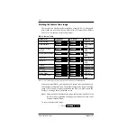
Page 18: ...ou must choose the Feature Code range that is not already in use Note After you choose a Feature Code range the Feature Code F903 used to select a range is disabled To change your choice of Feature Co...

Page 19: ...G and press OK 3 Record the serial number and press OK This serial number is required if you are upgrading a system to add Flash Voice Mail to an existing Flash ACD system 4 Press OK to initialize thi...

Page 20: ...o enable the Leading Digit If 9 is not the leading digit for Group Lists press CHNG and enter the new number The Group List leading digit can be any number from 0 to 9 Special Mailbox numbers automati...

Page 21: ...hat Flash is connected to We recommend you name the port FLASH For information about how to name the Flash DN refer to the Norstar System Coordinator Guide Norstar DN length Flash Voice Mail mailbox n...

Page 22: ...Voice Mail system to add Flash ACD you must enter a software key code and then press OK Instructions on how to obtain a software key code are in the Flash ACD Upgrade Guide 5 Press YES to have display...

Page 23: ...d the display shows System Ready and Exit The display then returns to the Norstar date and time Feature Code name Number Used By VML is Voice Mail Light VM is Voice Mail ACD is Automatic Call Distribu...

Page 24: ...and 99 Note On Flash ACD only systems the first feature used is Open mbox F9XX 3 Press NEXT to show the next Feature Code used by Flash Record this code on the Flash Programming Record and above in T...

Page 25: ...fault code is The display should show 2 If the display still shows Inactive feature check that the Feature Code range has been chosen by pressing 1 Enter the System Administration Feature Code The def...

Page 26: ...pherals connected to the station port which has the same DN that was assigned as the Control DN of an ACD queue power source to the Flash module is not damaged 4 After checking all the wiring reconnec...

Page 27: ...oard wallboard speeds must support 1200 baud hardware and software compatibility Note Flash supports XON XOFF cable type must be straight through modem cable Connecting the wallboard You must open the...

Page 28: ...using as the Real Time status device refer to the Flash ACD Set Up and Operation Guide Note The current version of Flash ACD supports wallboards that are manufactured by Spectrum Corporation For more...

Page 29: ...onfiguration programming 1 Enter the System Administration Feature Code The default code is 2 Enter the System Coordinator mailbox number and password and press OK Refer to Table 4 System Coordinator...

Page 30: ...24 Flash Installation Guide P0908433 01...

Page 31: ...sword refer to the Norstar Installer Guide that came with your KSU Access denied appears if you cannot use external feature inquiry from your telephone In use appears if someone else is using external...

Page 32: ...module earlier in this guide 7 Repeat steps 4 to 6 until you have tested all of the Feature Codes Note If None Registered appears all of the Feature Codes have been tested and removed The External Fe...

Page 33: ...rements 3 Electromagnetic interference 3 Environment conditions 3 F Feature Codes 17 determining 17 selecting 12 Flash Directory Number DN 15 Flash models 1 Flash initializing 9 Flash naming 15 Flash...

Page 34: ...pply 8 Prerequisites 2 Printer 2 R Reinstalling Flash 23 RS 232 terminal 2 S Screws 2 Software version 19 Special parts 2 Station port 1 Surge protector 2 T Terminal RS 232 2 U Upgrading to Flash 25 V...

Reviews:

Related manuals for Flash Basic 2