8
Flash Installation Guide
P0908433 01
Connecting the power supply
When you connect the power supply, the power to the Flash module is turned
ON.
To connect the power supply:
1.
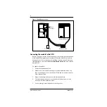
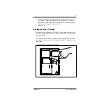
Open the module door. Locate the module power receptacle.
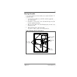
Refer to Figure 2 for the location of the power receptacle.
2.
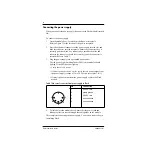
Place the cylindrical connector of the power supply into the slot, and
slide the connector into the receptacle. Ensure the connector's key is
correctly positioned (the key, indicated by a small dashed line and
indent in the connector, should face towards you as the connector is
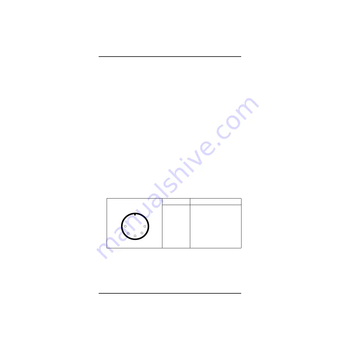
inserted). Refer to Table 1
.
3.
Plug the power supply into a grounded power outlet.
The red power Light Emitting Diode (LED) on the module should
light up. If the LED does not light up:
• Verify there is AC power.
• If there is power at the AC outlet, verify there is power output from
the power supply (voltage of 24 to 30 Vac rms across pins 1 & 3).
• If there is power output from the power supply, replace the Flash
module.
Table 1 Pin outs of connector from power supply to Flash
4.
To finish, close the module door. Ensure that the power cord and
teladapt cord(s) are routed through the cable guides on the module.
This completes connecting the power supply. You are now ready to begin
initializing Flash.
Pin
Connection
1
24 VAC rms
2
safety ground
3
24 VAC rms
4
no connection
5
no connection
1
4
2
3
5
Summary of Contents for Flash Basic 2
Page 2: ......


