21
P0908433 01
Flash Installation Guide
Connecting a wallboard to the Flash module
Connecting and using a wallboard to display call activity is optional if you
have Flash ACD. Before you install the wallboard, make sure you have an
RS-232 cable.
Note: Use these same steps to connect another real-time status device such
as a PC to the Flash module.
Important: The Flash module serial port is a standard RS-232 connector.
Make sure you use an appropriately constructed cable to connect the
wallboard to the Flash module.
Wallboard check list
The following wallboard specifications must be met before you connect the
wallboard:
❏
wallboard speeds must support 1200 baud
❏
hardware and software compatibility
Note: Flash supports XON/XOFF.
❏
cable type must be straight through (modem cable)
Connecting the wallboard
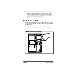
You must open the door of the unit before you can connect the wallboard. To
connect a wallboard:
1.
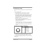
Plug the male end of the RS-232 cable into the RS-232 port of the
Flash module.
2.
Plug the female end of the DB-9 cable into the female 9 pin RS-232
connector on the RS-232/RS-485 Converter box, using a DB-9 to DB-
9 male adapter.
3.
Connect one end of the 4 conductor cable with the line filter (that is
supplied with the converter box) to the RS-485 connector on the RS-
232/RS-485 Converter box.
4.
Connect the other end of the 4 conductor cable to the RS-485
connector (labelled RS-232 in/RS-485 in) on the wallboard.
5.
Turn on the wallboard.
Summary of Contents for Flash Basic 2
Page 2: ......

