Page 16 of 220 Installing the hardware
553-3601-200 Standard 7.00 November 1998
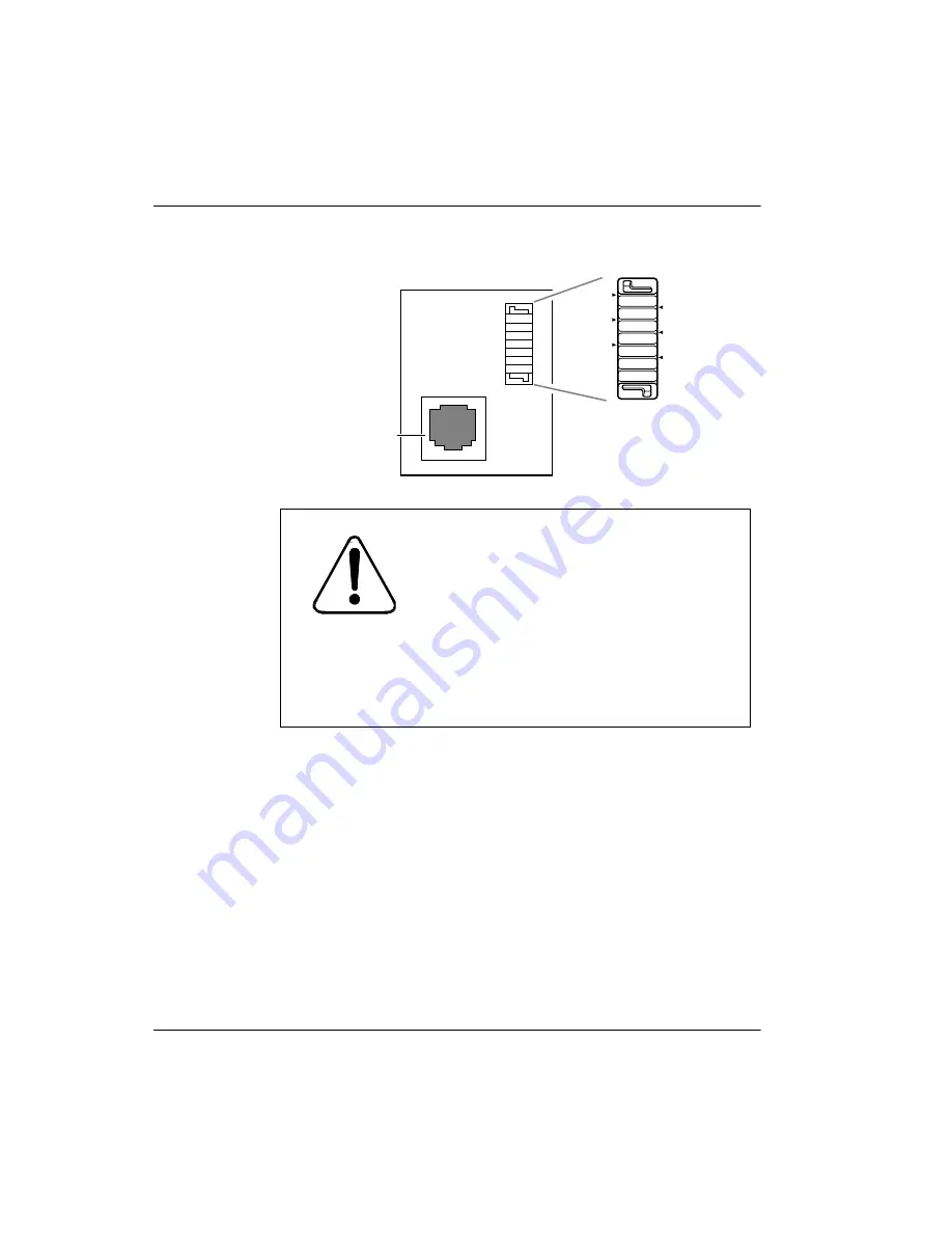
Figure 4 : Termination board
5.
Mount the Base Station onto the bracket, snapping it into position.
6.
Connect the power RJ11 jumper lead to the RJ11 jacks on the
termination board and the Base Station.
7.
Record the associated port number in the space provided on the printed
label affixed on the lower right corner of the mounting bracket.
Note:
Include the labeling information for each Base Station on the
completed installation floor plans and the Meridian Companion
Programming and Provisioning Record for reference.
8.
Slide the cover onto the bracket, using the guide to position it properly.
Snap the cover into place.
CAUTION!
Use UL approved primary and
secondary lightning surge arrestors in
series when installing TCM wiring
outdoors.
Any UL approved primary lightning surge
arrestor may be used, but only an Oneac
model 6-DP or ITW model MP1A-90-27
secondary lightning surge arrestor may be
used.
-PWR(1)
TCM
+PWR(1)
+PWR(2)
-PWR(2)
TCM
RJ11 jack
Summary of Contents for Meridian 1 PC Console Interface Unit
Page 2: ......
Page 10: ...Page x of x 553 3601 200 Standard 7 00 November 1998 ...
Page 78: ...Page 68 of 220 Installing the hardware 553 3601 200 Standard 7 00 November 1998 ...
Page 82: ...Page 72 of 220 System initialization 553 3601 200 Standard 7 00 November 1998 ...
Page 108: ...Page 98 of 220 Activating wireless communications 553 3601 200 Standard 7 00 November 1998 ...
Page 128: ...Page 118 of 220 Programming user options 553 3601 200 Standard 7 00 November 1998 ...
Page 204: ...Page 194 of 220 Troubleshooting 553 3601 200 Standard 7 00 November 1998 ...
Page 230: ...Page 220 of 220 Index 553 3601 200 Standard 7 00 November 1998 ...
Page 231: ......


