Page 26 of 220 Installing the hardware
553-3601-200 Standard 7.00 November 1998
1.
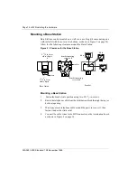
Position the screw holes for the RPI using the dimensions shown in
Figure 10.
To provide adequate ventilation and to prevent overheating, leave a
clearance of at least 5 in. around the RPI.
If mounting two RPIs, one above the other, leave a clearance of at least
1 ft between them to provide adequate ventilation and to prevent
overheating.
2.
Insert molly screws in the holes.
3.
Partially screw in two #10 2-in. screws for the keyholes.
4.
Open the hinged cover with a screwdriver by pushing in and then down
to release the catch on the right side, as shown in Figure 11. You can
remove the cover by taking it off its hinges.
5.
Hang the RPI on the two keyhole screws and tighten them.
6.
Install the remaining two screws.
7.
Feed in the power cord through the bottom of the RPI and route it
through the clip and around the strain relief support as shown in
Figure 9.
8.
Route the power cord to the input power jack just to the left of PSU 1.
Connect the plug to the jack.
Note: Labeling RPIs distinctively may help with diagnosis if there are
problems in the future.
Summary of Contents for Meridian 1 PC Console Interface Unit
Page 2: ......
Page 10: ...Page x of x 553 3601 200 Standard 7 00 November 1998 ...
Page 78: ...Page 68 of 220 Installing the hardware 553 3601 200 Standard 7 00 November 1998 ...
Page 82: ...Page 72 of 220 System initialization 553 3601 200 Standard 7 00 November 1998 ...
Page 108: ...Page 98 of 220 Activating wireless communications 553 3601 200 Standard 7 00 November 1998 ...
Page 128: ...Page 118 of 220 Programming user options 553 3601 200 Standard 7 00 November 1998 ...
Page 204: ...Page 194 of 220 Troubleshooting 553 3601 200 Standard 7 00 November 1998 ...
Page 230: ...Page 220 of 220 Index 553 3601 200 Standard 7 00 November 1998 ...
Page 231: ......


