Page 62 of 220 Installing the hardware
553-3601-200 Standard 7.00 November 1998
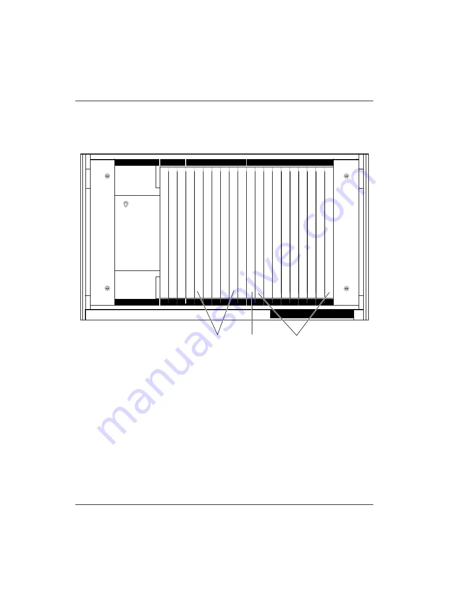
Figure 25 shows the card configuration on a CE/PE Module. The illustration
lists other cards that can be located on the CE/PE Module.
Figure 25: CE/PE Module—Meridian Companion possible placement of cards
Common/Peripheral Equipment
CE/PE Module
CE/PE Module
CE/PE pwr sup
1
2
3
4
5
6
7
8
9
10
0
1
2
3
4
5
6
7
8
9
FDI
CPU
Mem
SLP 0
SLP 4
SLP 8
SLP 12 SLP 16 SLP 20 Net/DTR
CPU/Mem
Net
IPE
QPC742 FDI
NTND01 ICM or QPC687 CPU
NTND02 MSPS or NT8D19 MMPS
NT8D17 Conf/TDS
NT8D18 Network/DTR
network-type cards
CMCC CMRCs/CMLCs/CMBCs
Summary of Contents for Meridian 1 PC Console Interface Unit
Page 2: ......
Page 10: ...Page x of x 553 3601 200 Standard 7 00 November 1998 ...
Page 78: ...Page 68 of 220 Installing the hardware 553 3601 200 Standard 7 00 November 1998 ...
Page 82: ...Page 72 of 220 System initialization 553 3601 200 Standard 7 00 November 1998 ...
Page 108: ...Page 98 of 220 Activating wireless communications 553 3601 200 Standard 7 00 November 1998 ...
Page 128: ...Page 118 of 220 Programming user options 553 3601 200 Standard 7 00 November 1998 ...
Page 204: ...Page 194 of 220 Troubleshooting 553 3601 200 Standard 7 00 November 1998 ...
Page 230: ...Page 220 of 220 Index 553 3601 200 Standard 7 00 November 1998 ...
Page 231: ......


