Page 66 of 220 Installing the hardware
553-3601-200 Standard 7.00 November 1998
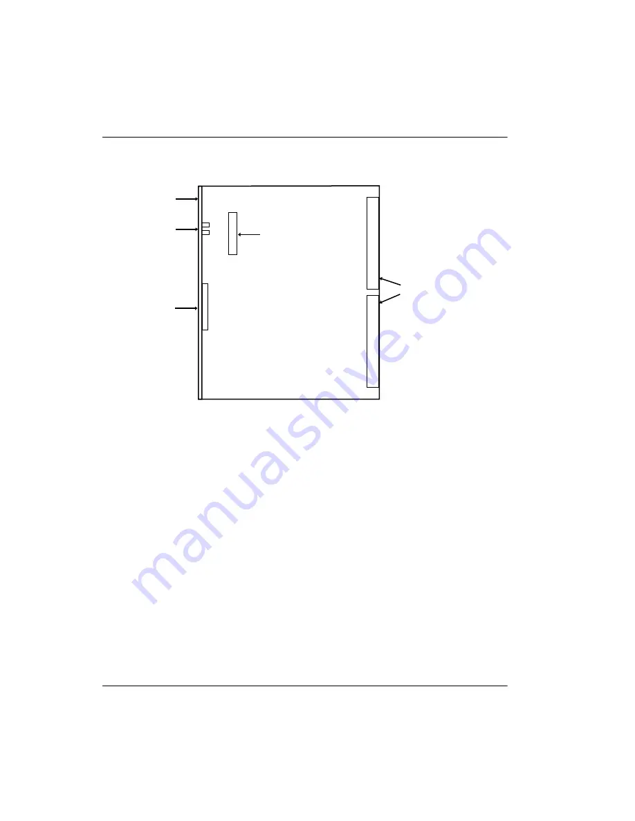
Figure 28: P2 plug location
5.
Fasten the ROM card securely to the standoffs.
6.
Install the CMCC on the IPE Module. The CMCC must be located to the
left of any CMRC, CMLC or CMBC.
7.
Connect the J1 plug of the last faceplate cable to the CMCC and verify
appropriate card LED behavior, as described in “Normal LED behavior
upon installation” on page 59.
Figure 29 illustrates how the system looks after you have installed cards and
interboard faceplate cable harnesses.
front
faceplate
LEDs
backplane connectors
J2
P2 connector
CMCC component side
Summary of Contents for Meridian 1 PC Console Interface Unit
Page 2: ......
Page 10: ...Page x of x 553 3601 200 Standard 7 00 November 1998 ...
Page 78: ...Page 68 of 220 Installing the hardware 553 3601 200 Standard 7 00 November 1998 ...
Page 82: ...Page 72 of 220 System initialization 553 3601 200 Standard 7 00 November 1998 ...
Page 108: ...Page 98 of 220 Activating wireless communications 553 3601 200 Standard 7 00 November 1998 ...
Page 128: ...Page 118 of 220 Programming user options 553 3601 200 Standard 7 00 November 1998 ...
Page 204: ...Page 194 of 220 Troubleshooting 553 3601 200 Standard 7 00 November 1998 ...
Page 230: ...Page 220 of 220 Index 553 3601 200 Standard 7 00 November 1998 ...
Page 231: ......


