Page 20 of 220 Installing the hardware
553-3601-200 Standard 7.00 November 1998
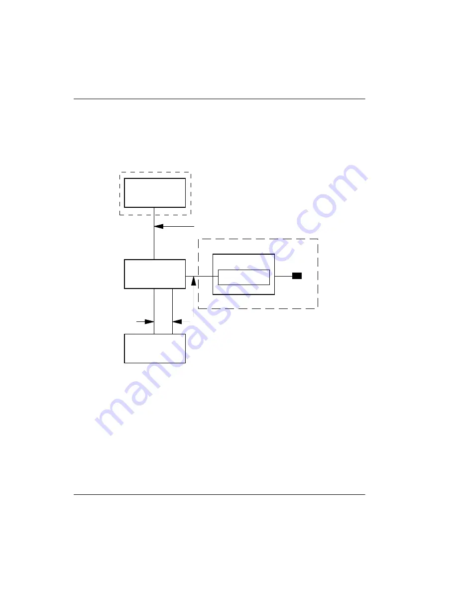
Figure 7 shows a configuration that would be suitable for a system that has an
existing MDF. Typically the MDF is located in the same room as the
Meridian 1 system, although it could be a closet MDF. In either case the Base
Stations are wired through the MDF rather than the RPI unit.
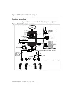
Figure 7: Base Station powering: RPI configuration option 2
An illustration of an RPI unit appears in Figure 8. Figure 9 illustrates RPI
components.
CMCC, CMRC or CMBC
MDF
Base Stations
main power
1- or 2- power pairs per Base Station
TCM cable
RPI
1-pair TCM wires
per Base Station
Meridian 1
RPI
output
Summary of Contents for Meridian 1 PC Console Interface Unit
Page 2: ......
Page 10: ...Page x of x 553 3601 200 Standard 7 00 November 1998 ...
Page 78: ...Page 68 of 220 Installing the hardware 553 3601 200 Standard 7 00 November 1998 ...
Page 82: ...Page 72 of 220 System initialization 553 3601 200 Standard 7 00 November 1998 ...
Page 108: ...Page 98 of 220 Activating wireless communications 553 3601 200 Standard 7 00 November 1998 ...
Page 128: ...Page 118 of 220 Programming user options 553 3601 200 Standard 7 00 November 1998 ...
Page 204: ...Page 194 of 220 Troubleshooting 553 3601 200 Standard 7 00 November 1998 ...
Page 230: ...Page 220 of 220 Index 553 3601 200 Standard 7 00 November 1998 ...
Page 231: ......


