background image


10 

Start-Up Procedures 

CAUTION: Break-in period 

Before initial use, open the drain valve and run the 
compressor without air tools attached and through open 
air line for 30 minutes to break-in pump parts. 

1.


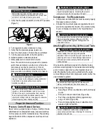
Verify that the pressure switch is in the OFF position. 
(Figure 5) 


Figure 5 


2.  Turn regulator counter clockwise to close. 
3.  Verify that the pressure gauge reads zero.    

4.  Open the drain valve so that air flow is permitted. 
5.  Turn the pressure switch to the ON position. 
6.  Adjust regulator to desired pressure. 
7.  Allow pressure in receiver tank to build.   


Note:  This electric model is equipped with a pressure 

switch that automatically turns the motor off when the 

tank pressure reaches its preset level.  Once air 
pressure in the tank drops to a preset low level, the 

pressure switch automatically turns the motor back on. 


WARNING: Overheating  

This compressor is equipped with “auto shut off”. 

However, failure to allow adequate cooling ventilation or 
a restriction in the intake airflow may cause the 
machine to overheat.  


WARNING: Inflatables/Low PSI tire 

Never use compressor to inflate small low-pressure 

objects, i.e., balloons/inflatables, small or low volume 
PSI tires. It is easy to over-pressurize them, causing 

them to rupture. Identify the inflation capacity of an 
object prior to filling it with air. Use a gauge to check the 
pressure regularly when inflating anything. 


Proper Air Hose and Tool Use 

Pressure Control Related Devices 

Never remove, adjust, bypass, change, modify or make 
substitutions for safety/relief valves, pressure switches 

or other pressure control related devices. Pressurizing 
beyond the limits of the compressor could result in an 
explosion. 


WARNING: Overpressurization hazard 

NEVER over-pressurize the receiver tank or air tools 
beyond nameplate capacity. Exceeding the pressure 
rating could cause them to explode or fly apart. 

Compressor - Tool Requirements  


Compressor and attachments must be sized properly 

for pressure and air volume. 


Consider the maximum pressure requirements and 
air volume requirements of each. (The volume rating 
of your compressor is listed in the “

Specifications

” 

section.)  


CAUTION: Tool overpressure hazard 

Do not operate this unit with any tool rated less than the 
maximum operating pressure of the unit (135 PSI) 

unless a properly sized regulator limiting pressure is 
used before the tool.   

Attaching/Disconnecting Air Hose and Tools 


CAUTION: High pressure stream hazard 

High-pressure air stream can pierce skin and underlying 
tissues, leading to serious injury and possible 

amputation. Such an injection injury can result in blood 
poisoning and/or severe tissue damage. High-pressure 
air stream can also cause flying debris and possible 
surface damage. 

On a fixed line distribution system the flexible hosing 
and tools would typically be connected at a terminating 
point. In some cases where a fixed system does not 
exist, the flexible hosing can be attached to the quick 

connect fitting on the main compressor outlet or after the 
user installed regulator. 


CAUTION: Air tools hazard 

Do not attach air tools to open end of the hose until 
start-up is completed and the unit checks out OK. 

Quick Connect Procedure: 


Keep finger off tool or activation switch until ready 
to use. 


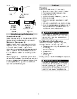
Pull quick connect collar back (Figure 6a). 


Push hose or attachment firmly against stop.   


Let go of collar (Figure 6b). 


Pull and rotate slightly (hose or attachment) to 
assure a tight connection. 


WARNING: Projectile hazard 

Air tool or attachment can become a projectile and 
cause serious personal injury or damage if not securely 
attached to the air hose.  

On 

Off 

Summary of Contents for 25653

Page 1: ...ol heads or attachments can ignite fuel or other flammable liquids or vapors in the vicinity Exceeding the maximum pressure for air tools or attachments could cause them to explode Burns Compressor pump motor and discharge tubing are hot surfaces that can cause burn injuries Electric Shock Operating equipment in wet conditions or where not properly grounded can cause electric shock Detailed safety...

Page 2: ...ssor for Spraying 11 Flammable Materials 11 Moisture in Compressed Air 11 Shutdown 11 Procedure 11 For Malfunction During Operation 11 Maintenance Repair 12 Maintenance Schedule Summary 12 Detailed Instructions Maintenance Repair 12 Inspect Safety Relief Valve 12 Inspect Air Filter 12 Inspect Compressor for Air Leaks 12 Change Pump Oil 13 Drain Receiver Tank and Inspect Tank 13 Check Drive Belt fo...

Page 3: ...3 Appendix A Lubricants and Compatibility 22 Alternate Lubricants 22 Limited Warranty 23 ...

Page 4: ...ersonal Protection Wear safety apparel during operation including safety glasses with side and top protection Adult Control Only Only trained adults should set up and operate the air compressor Do not let children operate Under The Influence Never operate or let anyone else operate the air compressor while fatigued or under the influence of alcohol drugs or medication Keep this manual for referenc...

Page 5: ... 20 gal 20 gal Power Requirements Dedicated NEMA Receptacles 5 15R 5 15R Volts 115V 230V 115V 230V Amps 15A 7 5A 15A 7 5A Motor Horsepower 2 HP 2 HP DIMENSIONS COMPONENTS Length 22 43 Width 23 22 Height 43 30 Weight 204 lbs 207 lbs SUPPLIES REQUIRED not included Pump Oil shipped with oil but refills required SAE 30 non detergent pump oil 4043 SAE 30 non detergent pump oil 4043 Pump Oil Capacity 16...

Page 6: ...ous situation which if not avoided will result in death or serious injury WARNING orange indicates a hazardous situation which if not avoided could result in death or serious injury CAUTION yellow used with the safety alert symbol indicates a hazardous situation which if not avoided could result in minor or moderate injury CAUTION yellow without the safety alert symbol is used to address practices...

Page 7: ...nual Step 2 Assembly 1 Insert the handle from the grip set into the mounting structure Secure using the bolts and washers if applicable from the grip set 2 Attach the tank wheels to the tank frame using the tank wheel bolts 3 Install the rubber pad sets onto the tank feet in the orientation shown Grip Set Includes Handle Qty 1 Bolt Qty 2 Model 25653 Only Grip Set Includes Handle Qty 1 Bolt Qty 2 W...

Page 8: ...t or air filter is not clean and functioning properly Do not allow debris to accumulate or block airflow Do not operate with a tarp blanket or cover surrounding the machine which blocks air flow Do not place any objects against or on top of the unit which can also block airflow or damage unit Electrical MUST be connected to a 115V 230 Volt single phase outlet having operating capacity of 15 amps o...

Page 9: ...in a well ventilated area to prevent health and fire hazards Prepare for Operation Make sure that any regular maintenance has been performed as prescribed in the Maintenance Repair section Drain receiver tank of any moisture Inspect for oil leaks Check for any unusual noise vibration Ensure the area around compressor is free from rags tools debris and flammable or explosive materials Ensure belt g...

Page 10: ...tion hazard NEVER over pressurize the receiver tank or air tools beyond nameplate capacity Exceeding the pressure rating could cause them to explode or fly apart Compressor Tool Requirements Compressor and attachments must be sized properly for pressure and air volume Consider the maximum pressure requirements and air volume requirements of each The volume rating of your compressor is listed in th...

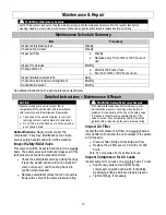
Page 11: ... Disconnect all tools 6 Drain air receiver tank by pulling safety relief valve 7 After all storage air discharges disconnect hoses 8 Once the tank pressure gauge registers under 10 PSI open the drain valve on the bottom of the tank to drain condensation moisture WARNING Risk of bursting Drain air receiver tank daily or after each use to prevent moisture buildup in the air tank Serious injury or de...

Page 12: ...ous safety hazards and will void the warranty Inspect Safety Relief Valve This valve should be inspected and tested on a weekly basis The safety valve automatically releases air if the tank pressure exceeds the preset maximum Check the safety relief valve by pulling the rings It is spring loaded and should not be stuck but come out about and then snap back into position when released Replace safet...

Page 13: ... CAUTION Pulley sheave hazard Improper pulley sheave alignment and belt tension can result in motor overload excessive vibration and premature belt and or bearing failure To prevent this from happening check the pulley sheave alignment and belt tension on a regular basis Belts will stretch from normal use When properly adjusted a 5 lb force applied to the belt between the motor pulley and the pump...

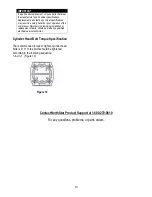
Page 14: ...ressor Major service including installation or replacement of parts should be made by a qualified electrical service technician Cylinder Head Bolt Torque Specification The recommended torque to tighten cylinder head bolts is 9 11 ft lbs Bolts should be tightened according to the following sequence 1 4 2 3 1 Figure 10 Figure 10 Contact NorthStar Product Support at 1 800 270 0810 For any questions p...

Page 15: ...e good contact on motor terminals or starter connections F Compressor viscosity too high for ambient temperature Drain existing lubricant and refill with proper lubricant G Poor ground Check all ground connections H Belt tension too tight or sheaves not aligned Check tension alignment i Air leaks in discharge piping Check tubing connections Tighten joints or replace as required J Poor power regula...

Page 16: ...16 Parts Explosions Model 25653 Rev A Pump not shown on this parts explosion ...

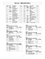
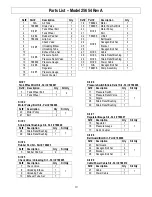
Page 17: ... Qty 3 Tank Wheel Bolt 1 2 4 Tank Wheel 1 Kit 5 Regulator Gauge Kit Part 788893 Ref Description Qty Kit Qty 15 Regulator 1 1 16 Pressure Gauge 1 17 Quick Coupler 1 Kit 2 Rubber Pad Nut Kit Part 788888 Ref Description Qty Kit Qty 5 Rubber Pad Set 1 2 33 Nut 1 Kit 6 Motor Pulley Bolt Kit Part 788896 Ref Description Qty Kit Qty 20 Motor Pulley 1 1 21 Bolt 1 Kit 3 Check Valve Unloading Kit Part 788890...

Page 18: ...18 Parts Explosions Model 25654 Rev A Pump not shown on this parts explosion ...

Page 19: ... 3 Tank Wheel Bolt 1 2 4 Tank Wheel 1 Kit 6 Pressure Switch Strain Relief Kit Part 788906 Ref Description Qty Kit Qty 11 Pressure Switch 1 1 12 Pressure Relief Valve 1 14 Nipple 1 28 Strain Relief Bushing 1 29 Strain Relief Bushing 1 Kit 2 Motor Pulley Bolt Kit Part 788896 Ref Description Qty Kit Qty 20 Motor Pulley 1 1 21 Bolt 2 Kit 7 Regulator Gauge Kit Part 788907 Ref Description Qty Kit Qty 15...

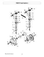
Page 20: ...20 788876 Pump Explosion Wing nut for 28 not shown ...

Page 21: ...at 1 N A 20 788882 Breathing cover 1 N A 21 N A Hexagon bolt 4 N A 22 N A Pulley 1 N A 23 N A Plate washer 1 N A 24 N A Hexagon bolt set 1 N A 25 N A Exhaust elbow 1 N A 26 N A Exhaust three way pipe 1 N A 27 N A Exhaust tube set 1 N A 28 788883 Air filter set 2 N A 29 N A Filter element 2 N A 30 N A Cylinder gasket 2 Kit 2 Kit 3 31 N A In Ex Valve seat 2 Kit 3 32 N A Valve seat gasket 2 Kit 2 Kit...

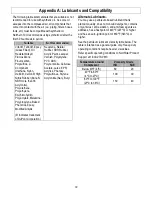
Page 22: ... Modified Alkyds indicates trademark of DuPont Corporation Neoprene Natural Rubber SBR Rubber Acrylic Paint Lacquer Varnish Polystyrene PVC ABS Polycarbonite Cellulose Acetate Latex EPR Acrylics Phenoxy Polysulfones Styrene Acrylonitile San Butyl Alternate Lubricants You may use a petroleum based lubricant that is premium quality does not contain detergents contains only anti rust anti oxidation a...

Page 23: ... of equal function Any misuse abuse alteration or improper installation or operations will void warranty Determining whether a part is to be replaced or repaired is the sole decision of NorthStar NorthStar will not provide for replacement of complete products due to defective parts Any costs incurred due to replacement or repair of items outside of a NorthStar approved facility is the responsibili...

Page 24: ...24 Assembled by Northern Tool Equipment Company Inc Burnsville MN 55306 NorthernTool com ...

Reviews: