7
Initial Set-Up
Step 1. Inspect & Unpack
Upon receipt, inspect air compressor for missing or
damaged parts. Verify that it is the compressor you
ordered.
See
“Component Identification”
section of this manual
for a diagram of the compressor and its components.
For
missing
components, contact Product
Support at 1-800-270-0810.
For
damaged
components, contact the freight
company that delivered the unit and file a claim.
If complete, fill out product serial number
information. See
“Limited Warranty”
section of
this manual.
Step 2. Assembly
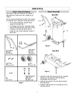
1.
Insert the handle from the grip set into the mounting
structure. Secure using the bolts and washers
(if applicable) from the grip set.
2.
Attach the tank wheels to the tank frame using the
tank wheel bolts.
3.
Install the rubber pad sets onto the tank feet in the
orientation shown.
Grip Set (Includes)
Handle – Qty 1
Bolt – Qty 2
Model 25653 Only
Grip Set (Includes)
Handle – Qty 1
Bolt – Qty 2
Washer – Qty 2
Model 25654 Only
Tank Wheel Bolt
Qty 2
Model 25653 & 25654
Tank Wheel
Qty 2
Model 25653 & 25654
Nut
Qty 2
Model 25653 only
Rubber Pad Set (Includes)
Rubber Foot – Qty 2
Washer – Qty 2
Bolt – Qty 2
Model 25653 & 25654
Model 25653
Figure 1
Figure 2
Figure 3
Model 25654
Handle
Bolt
Tank
Wheel
Bolt
Wheel
Tank
Summary of Contents for 25653
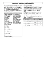
Page 3: ...3 Appendix A Lubricants and Compatibility 22 Alternate Lubricants 22 Limited Warranty 23 ...
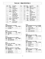
Page 16: ...16 Parts Explosions Model 25653 Rev A Pump not shown on this parts explosion ...
Page 18: ...18 Parts Explosions Model 25654 Rev A Pump not shown on this parts explosion ...
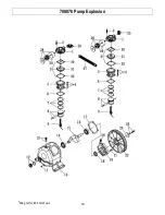
Page 20: ...20 788876 Pump Explosion Wing nut for 28 not shown ...
Page 24: ...24 Assembled by Northern Tool Equipment Company Inc Burnsville MN 55306 NorthernTool com ...


