Page 10 of 23
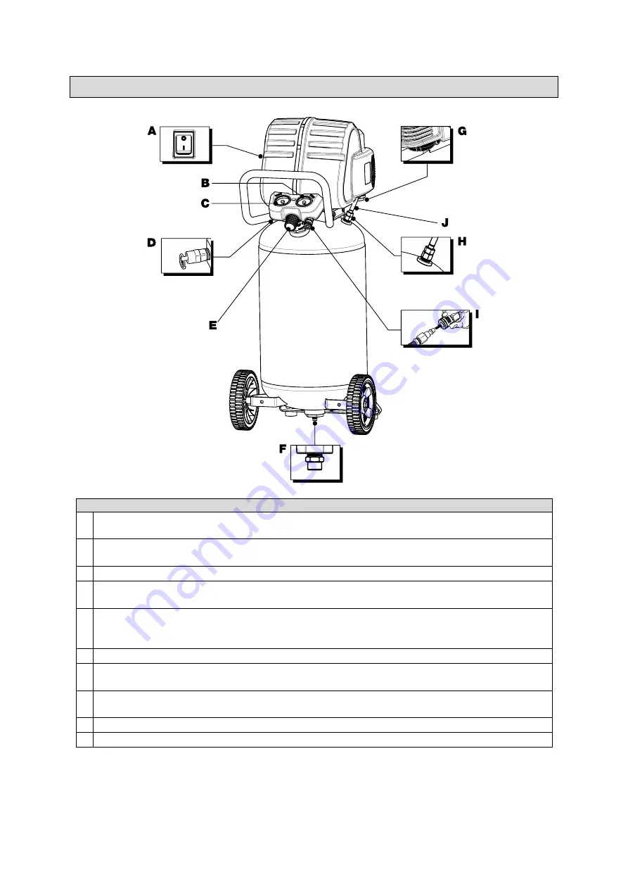
Main Parts of Air Compressor
Main Parts Description
A Power Switch:
This controls the power to the motor and also the cut-in/ cut-out pressure
settings. This switch serves as the Auto-On/Off positions for the unit.
B Tool Pressure Gauge:
Indicates the outgoing air pressure to the tool and is controlled by the
regulator.
C Tank Pressure Gauge:
Indicates the reserve air pressure in the tank.
D Tank Safety Valve:
Used to allow excess tank pressure to escape into the atmosphere.
This valve should only open when the tank pressure is above the maximum rated pressure.
E Regulator:
The air pressure coming from the air tank is controlled by the regulator. To increase
the pressure, turn the knob clockwise, and to decrease the pressure, turn the knob
Counter-clockwise.
F Tank Drain Valve:
Used to drain condensation from the air tank, located at bottom of tank.
G Air Intake Filter:
Provides clean air to the pump and must always be kept free of debris. Check
on a daily basis or before each use.
H Check Valve:
When the pump is not in operation, the valve closes to retain air pressure inside
the tank, an internal component.
I
Quick Connect:
Offers a quick release feature for attaching and removing the air hose.
J Outlet Tube:
Transfers
pressurized air from the air compressor pump to the tank.


