background image

SECTION THREE: Installing and wiring the 2201

957 Installation Manual, Revision C1

Page 21

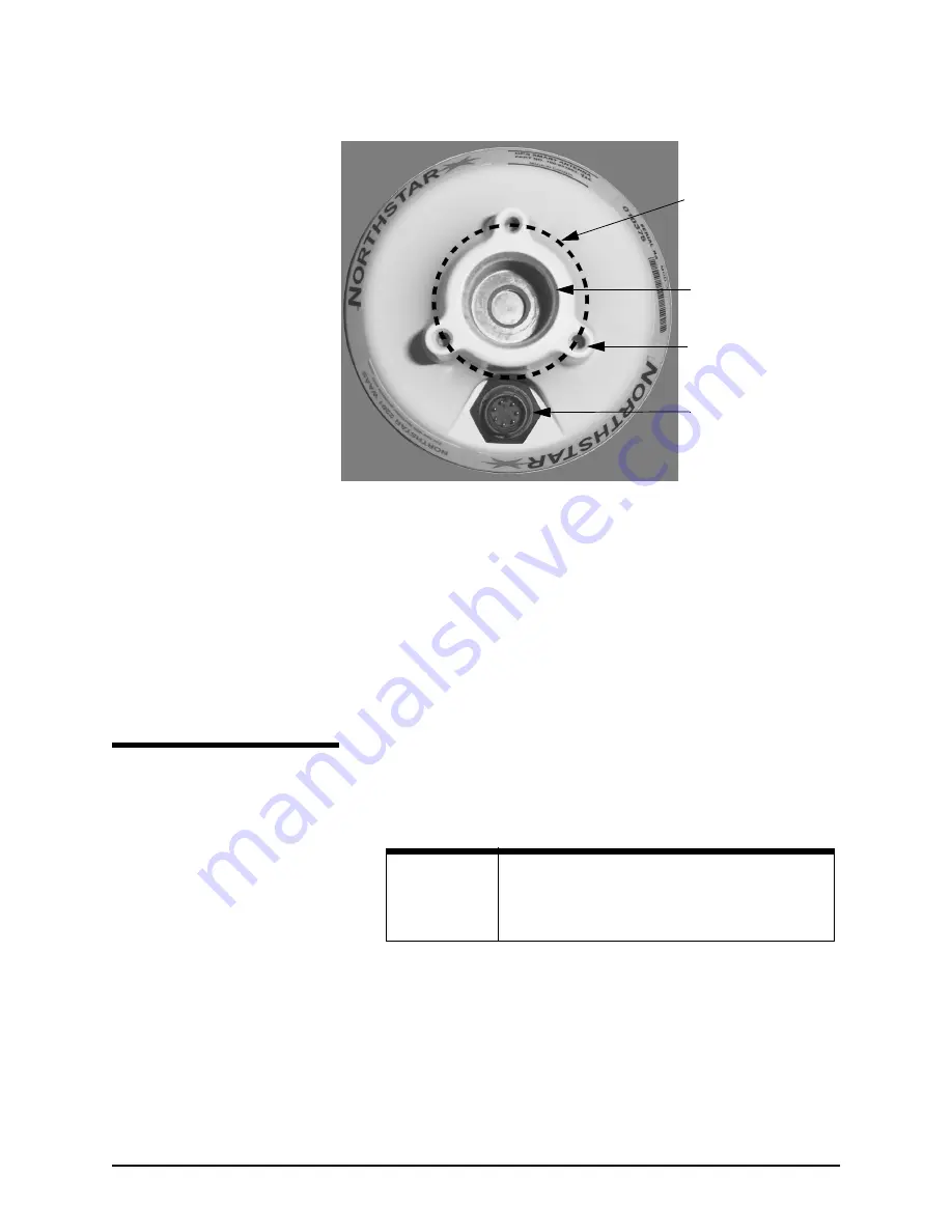
 Figure 10:  Mounting on a flat surface (viewed from below)

❷ 

Make sure the 2201 has enough mounting clearance so 

that you can easily connect the cable. For example, mount 
the 2201 on the edge of the deck, or drill a small hole in 
the deck or other surface to allow the cable to pass 
through.

Wiring the 2201

Connecting the 2201 to the

957

The 50-foot 957POD-CA cable connects the 957 with the 2201. 
Both ends of the cable are finished with 7-pin connectors that 
plug into the 2201 and 957: 

1.

Plug the 2201 end of the cable into the 2201, and the 
957 end into the 957 connector labelled “GPS.” Note: The 
cable’s connectors may look the same, but they are not 
interchangeable.


Connector receptacle with 7 
male contacts. Mating: 
Switchcraft EN3C7FC or 
equivalent. 

3x 3/16” - 32UNF - 2B x .48 
deep. Mounting holes 
equally spaced around a 
1.75” diameter circle.

1.00 -14UNS-2Bx 1.00 deep.

φφφφ

1.750

NOTE:

You can shorten the 957POD-CA cable, but do not
lengthen it. 

The cable


must be a maximum of 50

feet.

Summary of Contents for 957

Page 1: ...957 GPS WAAS CHART NAVIGATOR INSTALLATION MANUAL Revision C1 Part Number GM957IM Northstar Technologies 30 Sudbury Road Acton Massachusetts 01720 800 628 4487 978 897 6600 www northstarcmc com ...

Page 2: ...f the owner To be covered by this warranty the Northstar equipment must have been in normal use This war ranty does not apply to units with defects caused by improper installation physical damage abuse tampering lightning or other abnormal electrical discharge or to units with defaced or altered serial numbers or to units repaired by unauthorized persons or repaired in a manner that violates North...

Page 3: ...ing and wiring the 2701 25 Introducing the 2701 25 Installing the 2701 26 Wiring the 2701 27 Installing the AN205 P antenna 28 SECTION FIVE Checking out the system 31 Inserting a chart cartridge 31 Turning the 957 on and off 33 Installation test checklist 37 SECTION SIX Interfacing the 957 system 39 Wiring the connector pins 39 Configuring the NMEA output ports 41 Using 200 ppnm output 46 Configur...

Page 4: ...rvicing the 957 system 55 Troubleshooting 957 installation problems 55 Getting technical support 59 Servicing the 957 system 61 Returning a 957 system for service 62 Maintaining the 957 62 APPENDIX A 957 system technical specifications 63 ...

Page 5: ... the Northstar 1201 remote display Other optional interfaces include any NTSC compatible video input equipment such as a video camera TV DVD or VHS and the optional Northstar 2701 DGPS WAAS receiver used instead of the standard 2201 for WAAS and GPS plus radiobeacon differential Who should read this manual The Northstar 957 Installation Manual is for marine technicians who are installing interfaci...

Page 6: ...he 490 shipping carton Major installation steps The following list of recommended installation steps isn t a substitute for all the details in this manual To ensure that you meet all of the installation requirements be sure to read this entire manual and follow its recommendations closely Northstar suggests following the steps as outlined below PRE INSTALLATION Step 1 Check the shipping carton for...

Page 7: ...IK optional remote control and batteries P N 957RC MOUNTING AND WIRING Step 1 Review all of the installation requirements as described in Section Two and Section Three Step 2 Make sure you have all the right tools before starting the installation Step 3 Install the 957 see Mounting the 957 beginning on page 6 Step 4 Install the 2201 and cable see SECTION THREE Installing and wiring the 2201 beginn...

Page 8: ... by performing a functional test including checking for GPS WAAS signals For help see Installation test checklist on page 37 and Table 10 Troubleshooting the 957 installation on page 55 Step 3 Optional Connect the 957 to a remote display or a video source such as a video camera see SECTION SIX Interfacing the 957 system starting on page 39 Step 4 Configure the NMEA output ports see Configuring the...

Page 9: ...power is left on or turned on during the installation fire electrical shock or other serious injury may occur Be sure that the voltage of the power supply is compatible with the 957 s voltage rating 10 to 36 volts DC Connecting to the wrong power supply can cause fire or damage to the equipment Be sure to ground the equipment to prevent electrical shock and mutual interference Be sure to use the p...

Page 10: ...oosing the best location Choose the mounting location carefully before you drill or cut The display screen is high contrast and anti reflective and is viewable in direct sunlight but for best results install the 957 out of direct sunlight See the figure below for additional mounting recommendations CAUTION Make sure that the 957 doesn t interfere with any other on board systems Check all other sys...

Page 11: ...should be installed in an accessible location dry where the operator can easily use the controls and clearly see the display screen Be sure to leave a direct path for all of the cables Regardless of the type of mounting the location should have minimal glare from windows or bright objects If the 957 is yoke mounted low tilt the 957 back for best viewing contrast ...

Page 12: ...eight requirements for flush mounting the 957 For further details see the full size Northstar 957 Flush Mounting Template part number GT957 This template should be used to drill the mounting holes and cut the mounting panel in the exact recommended locations CAUTION Keep the following safe compass distance from the 957 1 0m standard 0 8m steering CAUTION When flush mounting be sure to mount the 95...

Page 13: ...SECTION TWO Installing and wiring the 957 957 Installation Manual Revision C1 Page 9 Figure 2 957 flush mount clearance dimensions ...

Page 14: ...cables Leave clearance space as follows at least 2 inches of space all around the sides and the top at least 2 5 inches of space in the back for all of the cables and connectors at least 2 25 inches of space in the front for opening and closing the chart cartridge door and inserting and removing a chart cartridge For an illustration of the recommended clearances see Figure 3 and Figure 4 on the fo...

Page 15: ...SECTION TWO Installing and wiring the 957 957 Installation Manual Revision C1 Page 11 Figure 3 957 yoke mount dimensions side 6 1 1 9 8 2 2 5 12 4 2 3 ...

Page 16: ...SECTION TWO Installing and wiring the 957 Page 12 957 Installation Manual Revision C1 Figure 4 957 yoke mount dimensions front 13 5 11 6 12 4 ...

Page 17: ...uidelines illustrated in Figure 5 below Figure 5 Avoiding cable wiring shortcuts DON T DO THIS DO THIS Do not make sharp bends in the cables Do not run cables in such a way that might allow water to flow down into the connectors Do make drip and service loops Do tie wrap all cables to keep them secure If cables are shortened lengthened or re terminated do seal and protect all wiring connections Do...

Page 18: ...nterface connectors back of 957 NMEA connector VIDEO connector Power connector GPS connector AUX connector VGA connector Table 1 Interface connector functions Connector name Connector function s Connects to NMEA NMEA I O 18 pin port NMEA 1 input output NMEA 2 input output Honk alarm 200 ppnm NMEA devices autopilots etc same as NMEA 1 Remote honk alarm or speed indicator GPS Antenna 7 pin RS232 por...

Page 19: ... fuse size should match the size of the wiring on the vessel See the NMEA or the American Boating and Yachting Counsel specifications to find the correct fuse to use with your cable For the best protection from noise connect the power cable directly to the battery or dedicated electronics buss The green ground wire should be connected to ship s ground directly AUX Auxiliary 6 pin auxiliary NMEA po...

Page 20: ...tact The wires in the power cable must be connected as follows red positive black negative green ship s ground NOTE Ground the 957 to the vessel to eliminate interference Without an earth grounding performance may be reduced Secure the green wire to the vessel s nearest grounding point If a noise free earth grounding point isn t available cap and insulate the green wire it shouldn t be used when a...

Page 21: ...also receives Wide Area Augmentation System WAAS differential correction signals When connected to the 957 the 2201 provides the 957 with WAAS enhanced GPS position information For the 2201 s technical specifications see Table 15 2201 technical specifications on page 64 CAUTION Do not open the 2201 There aren t any serviceable parts inside Unauthorized tampering will automatically void the warrant...

Page 22: ... the best mounting location Before you drill or cut choose a mounting location that meets the following criteria The 2201 should be mounted where there s enough mounting clearance to easily connect the cable low on the vessel since side to side motion caused by the vessel s rolling can degrade speed over ground SOG and course over ground COG readings NOTE Before permanently installing the 2201 try...

Page 23: ...or objects that could shadow the 2201 but where there s an adequate view of the sky To avoid mutual interference among different antennas on the vessel see the recommendations in Figure 8 below This figure shows the minimum distances that should separate GPS WAAS antennas from other antennas and physical mounting surfaces Normally these guidelines produce a relatively trouble free installation How...

Page 24: ...weight of the cable use a tie wrap or similar near the 2201 to hold the cable s weight Figure 9 Mounting position for a standard mast mount Using a flat surface You can mount the 2201 onto a deck or any other flat surface Using the three screws and washers provided mount the 2201 onto the flat surface using three holes on a 1 75 inch diameter circle see Figure 10 below An optional magnetic mount a...

Page 25: ...ot 957POD CA cable connects the 957 with the 2201 Both ends of the cable are finished with 7 pin connectors that plug into the 2201 and 957 1 Plug the 2201 end of the cable into the 2201 and the 957 end into the 957 connector labelled GPS Note The cable s connectors may look the same but they are not interchangeable Connector receptacle with 7 male contacts Mating Switchcraft EN3C7FC or equivalent...

Page 26: ... Prepare each wire for insertion into its solder cup by stripping it and tinning it 3 Carefully solder each wire to the appropriate cup as described in Table 2 below 4 Slide the backshell down the cable and screw it onto the connector body It should be hand tight 5 Using the supplied screws screw the strain relief onto the backshell 6 Slide the heat shrink tubing onto the connec tor Be sure to lea...

Page 27: ...957 has four settings for differential operations For instructions on choosing the correct setting see Selecting differential options starting on page 36 Remote power on Ship s power control Black 5 Power gnd system gnd White 6 Power in 9 36 VDC Red 7 Table 2 Wiring connections for 2201 cable cont Description Wire color Pin ...

Page 28: ...SECTION THREE Installing and wiring the 2201 Page 24 957 Installation Manual Revision C1 ...

Page 29: ...con receiver packaged into a self contained enclosure The 2701 receives differential corrections from ground based radiobeacons as well as from satellites transmitting WAAS differential signals For the 2701 s technical specifications see Table 16 2701 technical specifications on page 65 CAUTION Do not open the 2701 There aren t any serviceable parts inside Unauthorized tampering will automatically...

Page 30: ...ged aluminum enclosure with a mounting flange gaskets and watertight connectors Though designed to withstand the marine environment the unit is not completely waterproof Protect the 2701 by installing it where water won t contact it directly or enter it by following data power or antenna cables Mounting the 2701 You can mount the 2701 either horizontally or vertically using the appropriate mountin...

Page 31: ...e cable are finished with connectors that plug into the 2701 and 957 Plug the cable s 25 pin connector into the 2701 and the 7 pin connector into the 957 connector labelled GPS In case you have to remove one of the cable s connectors be sure to re fabricate the cable using the wiring connections described in the table below Table 3 Wiring connections for 2701 cable 957 connector 7 pin 2701 connect...

Page 32: ...at least six feet away from objects that can shade GPS or differential signals 3 6 GPS TX1 Green 4 20 BDM TX1 Brown 5 12 Power CTL Black or Gray 6 13 GND White 7 25 Power Red 6 NC Drain Wire NC KS131 Foil Shield Table 3 Wiring connections for 2701 cable cont 957 connector 7 pin 2701 connector 25 pin Function NOTE Double check all wiring if you re fabricate the cable A small but significant number ...

Page 33: ...d length Note Installations that require a cable length from 50 to 100 feet should order the AN206 combo antenna and a 100 foot length of coaxial cable from the Northstar Sales Department Don t make any tight bends in the cable and fasten it along its length to avoid chafing or whipping or any kind Coil up any unused length of cable Be sure that the cable connectors are securely fastened CAUTION D...

Page 34: ...SECTION FOUR Installing and wiring the 2701 Page 30 957 Installation Manual Revision C1 ...

Page 35: ... corner of the 957 Before inserting a Navionics chart cartridge make sure its label is facing up and that the cartridge is oriented as shown in Figure 13 below Insert the cartridge gently but firmly into position with one straight smooth motion If you only partially insert the cartridge stop then move the cartridge again it may get stuck in an awkward position ...

Page 36: ...hat you don t expose the cartridge to any environmental damage please use caution when changing the cartridge Be careful when inserting the cartridge into the 957 see description above and illustration at right When you re not using the cartridge store it in a clean dry place away from heat humidity and dust Improper handling and storage of the cartridge may damage the 957 Such damage isn t covere...

Page 37: ...ainst relying on the 957 s chart cartography as the only means of safe navigation To continue accept the warning message by pressing any one of the five function keys CHART STAR STEER NAV LOG or WAYPTS ROUTES located below the display screen To identify the cartridge inside the 957 press the CHART SETUP menu key to the right of the CHART screen to display the CHART STATUS screen the cartridge door...

Page 38: ...t all cartridges will have a date especially older ones in this case only the word PRESENT is shown rather than the name and date Checking satellite status The 957 uses a high performance GPS receiver as its primary source of position data augmented by either the WAAS satellite system or the radiobeacon differential DGPS system if the 957 is connected to the optional Northstar 2701 receiver To see...

Page 39: ...e quality of their signals by looking at each satellite s Signal to Noise Ratio SNR The higher the ratio the better the quality While the U S government identifies WAAS satellites by their pseudo random number PRN a three digit number ranging from 120 to 138 the 957 identifies them by two digit numbers ranging from 33 to 51 For example the satellite for the Atlantic Operating Region AOR is PRN 122...

Page 40: ...al corrections but if the 957 is connected to the optional 2701 the 957 will automatically switch to radiobeacon corrections if and when WAAS becomes unavailable or is less accurate than radiobeacon About auto dimming mode When the display screen is at full brightness if the 957 gets too hot inside due to the outside temperature and sunlight the display screen will automatically dim Auto dimming h...

Page 41: ...that the CHART screen is displayed 3 Confirm that the DIFFERENTIAL OPERATIONS option is at the desired setting If not press the STAR key to display the OPTIONS SERVICE INFO screen then press the RECEIVER OPTIONS menu key to display the RECEIVER OPTIONS screen Press the EDIT key change it to the desired setting then press the ENTER key For more in depth information about troubleshooting the 957 ins...

Page 42: ...SECTION FIVE Checking out the system Page 38 957 INSTALLATION MANUAL Revision C1 ...

Page 43: ...ector RS 232 input and output on the 18 pin NMEA connector RS 422 NMEA input and output on the 6 pin AUX connector Composite video input on the VIDEO connector VGA output on the VGA connector You can display the list of wires for the connectors Press the STAR key to display the OPTIONS SERVICE INFO screen then press the PORT SETUP OPTIONS menu key to display the PORT SETUP OPTIONS screen then pres...

Page 44: ...violet 12 NMEA port 1 output B gray 7 NMEA port 1 output ground blue with white stripe 8 NMEA port 2 input A white with brown stripe 6 NMEA port 2 input B brown with white stripe 2 NMEA port 2 input ground white 5 NMEA port 2 output A yellow 15 NMEA port 2 output B orange 11 NMEA port 2 output ground black 10 RS 232 ground tan 17 RS 232 RX green 16 RS 232 TX red 18 External ground foil drain white...

Page 45: ...display the PORT SETUP OPTIONS screen 2 Press the PORT 1 SETUP or PORT 2 SETUP menu key to display a list of seven data format control options as shown below Table 6 Aux connector pins Description Wire color Pin Shield Gnd brown 1 Remote On Gnd green 1 Remote On white 2 NMEA AUX In B black 3 NMEA AUX Out B orange 4 NMEA AUX Out A violet 5 NMEA AUX In A blue 6 Pin 1 on the AUX port requires two con...

Page 46: ...in the late 1970 s required by certain older autopilots None turns the outputs off for when the 957 isn t connected to an external device 0183 Ray is used when transmitting receiving position information to or from Raytheon equipment In Raytheon s Table 7 Setup options for the NMEA port Setting Choices OUTPUT FORMAT see below choose 0183 V2 1 0180 NONE 0183 RAY or DATAM CDX NMEA 0183 TALKER ID see...

Page 47: ... meaning of these sentences see the NMEA interface specifications document published by the NMEA The sentences to be output are followed by the word ON those that won t be output have two dashes indicating that they re off Some devices can t handle all these sentences correctly so you can customize the output here by turning individual sentences on or off In general you may want to turn on only th...

Page 48: ... to LC GP or II to match what the listener device is expecting 1 Check the listener device s instruction manual to determine which talker ID codes it will respond to 2 At the PORT 1 SETUP or PORT 2 SETUP screen press the CURSOR PAD to highlight the NMEA 0183 TALKER ID option then press the EDIT menu key 3 Scroll through the three choices using the CURSOR PAD to make your selection and press the EN...

Page 49: ...when specifying either NMEA 0183 NMEA version 2 0 or Raytheon RAY 0183 Because there isn t enough time to transmit all available sentences within one second you must select for output only those that are needed If you select more sentences than can be output in one second the 957 displays the following error message SORRY CAN T DO THAT TOO MANY SENTENCES FOR 1 SEC INTERVAL In this case you must se...

Page 50: ...through the choices to make your selection To apply this chosen datum to the lat lon coordinates in the NMEA 0183 output sentences press the ENTER key Using 200 ppnm output The 957 provides an open collector transistor output on pin 14 that s programmed to produce 200 pulses per nautical mile The emitter of the NPN transistor is connected to ground and its collector connects to the output pin see ...

Page 51: ...t a PC for downloading your waypoints or for uploading 957 software updates The following sections describe the RS 232 port s settings for SC 104 in and copy port 1 and 2 Using SC 104 in THE SC 104 IN setting lets the 957 accept optional differential corrections from any source that transmits the standard SC 104 data stream When using SC 104 IN be sure that the BAUD RATE setting also matches the b...

Page 52: ...PY PORT 2 selection by pressing the EDIT menu key then pressing the CURSOR PAD to change the selection then pressing the ENTER key The unit will now copy and output the specified port s data format through the RS 232 port to an external device Using the port off setting Use this setting when you don t need the RS 232 port s input or output functions About the diagnostic setting This setting is onl...

Page 53: ...heck the manufacturer s instructions for details After you ve connected the 957 to the video device check the connection by pressing the VIDEO menu key available on most 957 s screens to see the video image on the screen For instructions on moving the image and changing its size see the Northstar 957 Operator s Manual part number GM957UG Connecting with a radar device The 957 can be set to interfa...

Page 54: ...sfer waypoints and routes to or from must be using software version 3 12 or higher Assembling the cable To assemble the cable 1 Cut the cable to the desired length 2 Slide the following parts onto each end of the cable in the following order connector backshell rubber strain relief boot that fits inside the backshell twist lock also known as a quarter turn ensuring that it s facing in the correct ...

Page 55: ... 1 Ground shield 1 Ground shield 2 No connect 2 No connect 3 Aux In B 5 Aux Out B 4 Aux Out A 6 Aux In A 5 Aux Out B 3 Aux In B 6 Aux In A 4 Aux Out A 957 6 PIN AUX CONNECTOR 957 6 PIN AUX CONNECTOR 1 2 3 4 5 6 1 2 3 4 5 6 No connect Aux input A Ground shield Aux output A Aux input B Aux output B Shield termination Aux output A Aux input A Aux output B Aux input B Ground shield Pin number No conne...

Page 56: ...g side view solder cup 952 951 941 10 PIN AUX CONNECTOR Pin number 1 2 3 4 957 6 PIN AUX CONNECTOR Pin number 5 6 7 8 9 10 1 2 3 4 5 6 No connect No connect No connect No connect No connect Aux input B Ground shield Aux output B Aux input A Aux output A Shield termination Aux input B Ground shield Aux output B Aux output A Aux input A No connect ...

Page 57: ...s the IMPORT DATA or EXPORT DATA menu key d Press the TEST COMM menu key 8 The message should read REMOTE LINK OK If so the hardware connection is now complete and the two units can now transfer all waypoints and routes between them Setting the anchor watch alarm honk The anchor watch alarm function is used to set the 957 to honk in addition to beep once you ve connected a honker to pin 14 on the ...

Page 58: ...73 060 or an equivalent Figure 19 Pin 14 honk alarm connection A continuous honking sequence will begin either when the vessel moves outside the specified anchor alarm radius or when the navigation source becomes unavailable once you ve set the anchor watch alarm to honk For detailed instructions about this feature see the Northstar 957 Operator s Manual part number GM957UG ...

Page 59: ...er the 957 s installation are described in the tables below Table 10 Troubleshooting the 957 installation Problem Area Symptom Possible Solutions Reasons POWER DISPLAY Pressing the PWR key doesn t start the 957 The 957 powers up beeps but there isn t any video Check the fuse and the power to the 957 The display may have failed Call your Northstar dealer or the Northstar Service Department ...

Page 60: ...heck that the video image is turned on press STAR to display the VIDEO SETUP screen Check the cables and the connectors Check that the video equipment is working properly SYSTEM System lock ups Hardware related The system locks up on a random basis with no apparent pattern The system locks up when using a chart card System fails any initial self tests Possible internal hardware failure call the No...

Page 61: ... on page 19 Make sure the antenna is clean and not covered with ice snow or exhaust soot You re having difficulty obtaining WAAS satellites Check that WAAS is available in your operating area Reset the 957 s satellite elevation setting to its default 10 degrees Check that the 957 s DIFFERENTIAL OPERATIONS option is set to either WAAS or AUTO The following error message appears on the 957 display C...

Page 62: ... antenna is clean and not covered with ice snow or exhaust soot You re having difficulty obtaining WAAS satellites Check that WAAS is available in your operating area Reset the 957 s satellite elevation setting to its default 10 degrees Check that the 957 s DIFFERENTIAL OPERATIONS option is set to either WAAS or AUTO The following error message appears on the 957 display COMM FAIL TOO FEW SATS Wit...

Page 63: ...00 PM Eastern Time Monday through Friday excluding major holidays If you want to buy parts or would like to request brochures or have product questions contact the Northstar Sales Department as described in the table below NOTE Please have the 957 s serial number available on the back of the unit or on the OPTIONS SERVICE INFO screen ready before contacting Northstar s Service Department Table 13 ...

Page 64: ...rvice request form for sending systems back service status request form for systems currently under repair warranty registration form for registering new products Online information sources For up to date WAAS information visit the following websites The status of WAAS implementation http gps faa gov programs waas implementation_Status implementation_status htm U S government s WAAS GPS website ht...

Page 65: ...re updates aren t covered by the Northstar warranty Servicing the 957 system 957 repairs are performed only by authorized Northstar dealers or at the Northstar factory Service includes a complete hardware and software check out For a system under warranty shipping charges to the factory are the only cost for factory repair The repaired 957 will be returned via prepaid economy ground freight units ...

Page 66: ...naround time freight charges and payment arrangements The 957 should be shipped only in a properly designed carton with packing material and to the Northstar factory at the following address Northstar Technologies Service Department 30 Sudbury Road Acton MA 01720 USA Maintaining the 957 Basic maintenance At the end of the day wipe the 957 off with a damp cloth Cover it with the sunshield to protec...

Page 67: ... to a PC with appropriate software High contrast anti reflective screen Waterproof chart cartridge door One VGA out port connects to Northstar 1201 monitor and others Large easy to use backlit controls One VIDEO in port Easy interfacing I O plugs NMEA input sentences WPL and others 0 degrees Celsius 55 degrees Celsius max 95 relative humidity noncondensing 10 36 volts DC power 200 PPNM speed outpu...

Page 68: ...200 baud Default baud rate 9600 Performance Environmental Acceleration 4 Gs 39 2 m s2 Jerk 2 m s3 Operating temperature 30 to 75 C standard Velocity 1852 km h 514 m s max Storage temperature 55 to 90 C Position accuracy 3 m 2dRMS Humidity SAE J1455 4 2 Procedure I II Time to first fix TTFF Hot start 20 seconds typical with current almanac Warm start 45 seconds typical with current almanac Cold sta...

Page 69: ...lar error probability CEP DGPS 2 m circular error probability CEP WAAS Time to first fix TTFF Hot start 20 seconds typical with current almanac position time and ephemeris Warm start 45 seconds typical with current almanac position time and ephemeris Cold start 2 minutes typical no almanac position and time With WAAS acquisition add 30 seconds typical max 1 minute Re acquisition time 1 second typi...

Page 70: ...APPENDIX A 957 system technical specifications Page 66 957 INSTALLATION MANUAL Revision C1 ...

Reviews: