23
Reference Manual
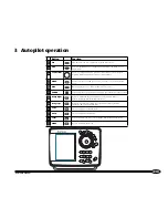
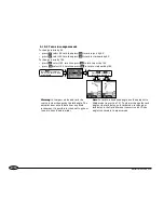
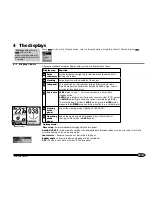
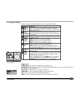
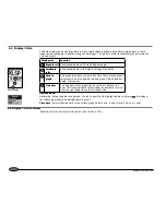
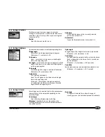
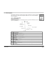
Displays a standard autopilot display with just the essential autopilot data.
Options menu:
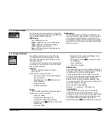
Deviation bar
Selects what data is displayed by the deviation bar.
Auto Rd/CE/XTE
– Automatically switches the deviation bar between rudder, course error and cross track error
depending on the operating mode.
Course error
– Shows course error using the deviation bar.
Rudder angle
– Shows a rudder angle gauge using the deviation bar.
XTE
– Shows a cross track error bar using the deviation bar.
Header
—
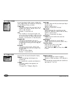
Menu for configuring the data header in this display (see section 5).
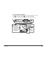
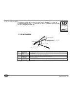
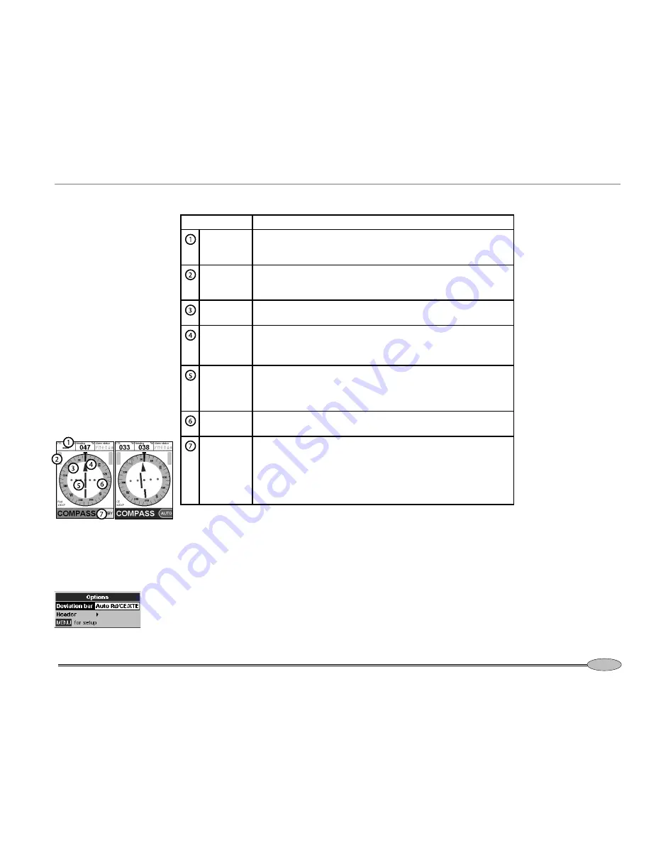
Display area
Function
Data
Header
Customizable data cells. Each display page has a separate
header configuration. Default: Course to steer, Heading, Alarm
Status (see section 5).
Drive
indicators
Left and right boxes ‘fill up’ to indicate when the autopilot is
driving the rudder and how much power is being used by the
drive system
Compass
card
Compass card rotates to show the heading of the vessel under
the lubber mark.
Course
arrow
STBY
mode: points to the current heading
AUTO
mode: points to the set course, except for:
GPS
mode: points to the bearing to waypoint
Deviation
bar
Moves laterally to show course information.
Note:
This bar can be configured to display different items.
Default: Automatically switches between Rudder angle, Course
error and Cross track error.
Deviation
scale
Indicates what data the deviation bar is currently showing and
the magnitude
Mode
panel
Left hand side: shows the steering mode (COMPASS, GPS, WIND)
Right hand side: shows the operating mode (Standby, Auto,
H-Steer) inside a colored tab.
Panel changes to blue when in
AUTO
mode. The colored tab
is yellow in
STBY
mode, green in
AUTO
mode, magenta in
H-STEER
mode and red when there is a critical alarm.
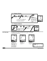
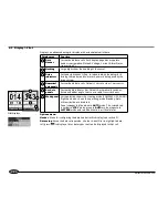
4-3 Display > Compass
Compass displays

